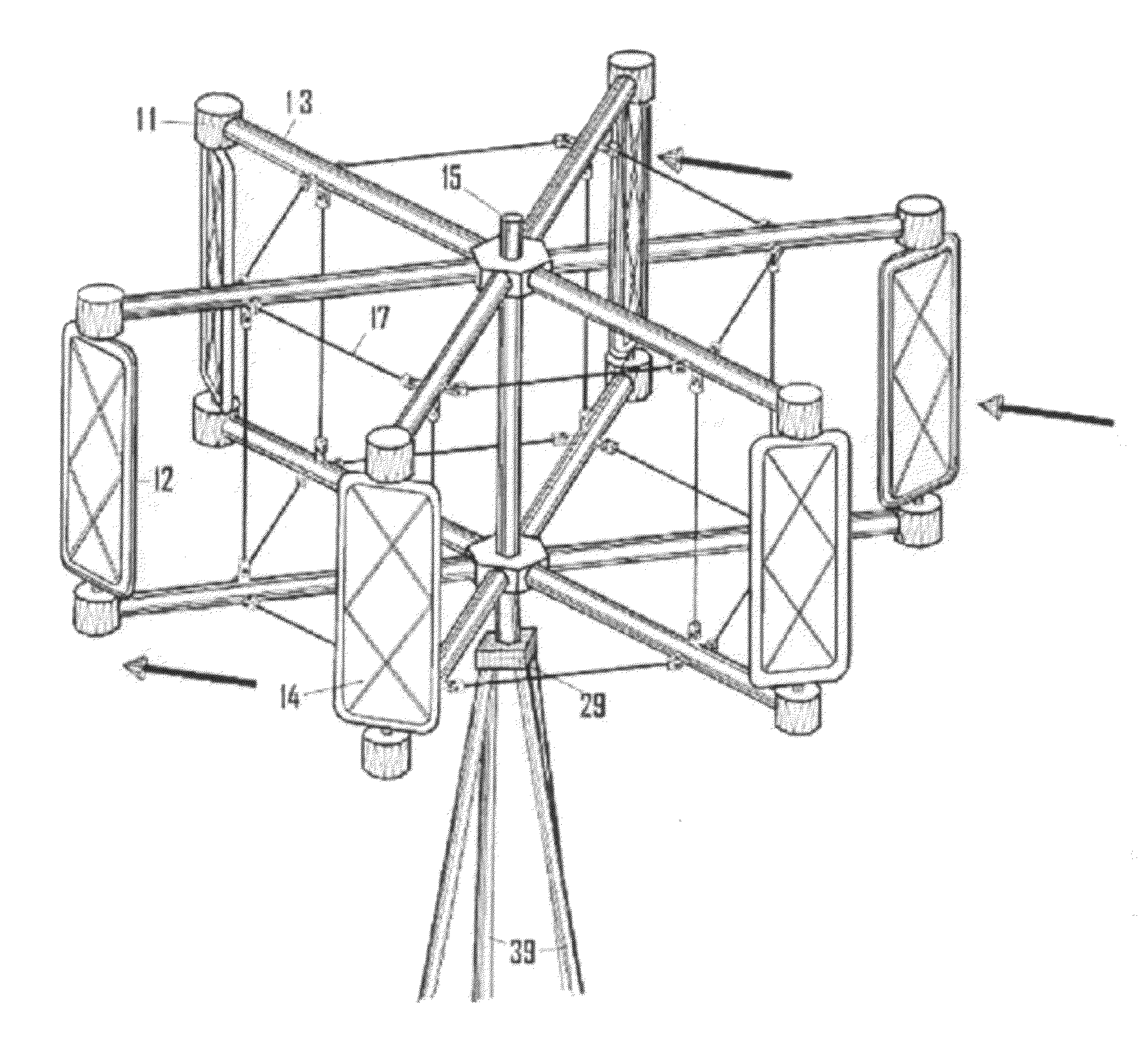
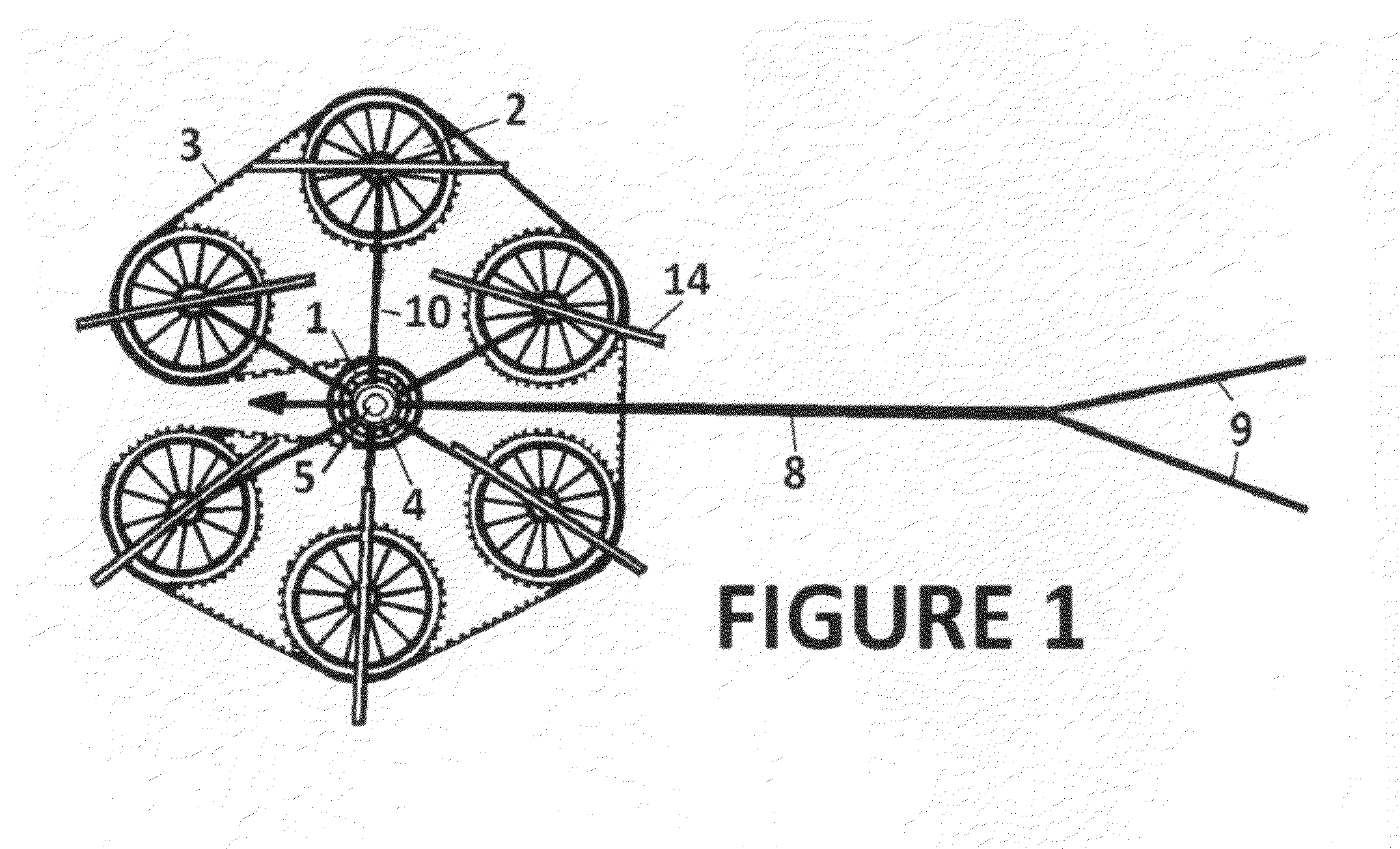
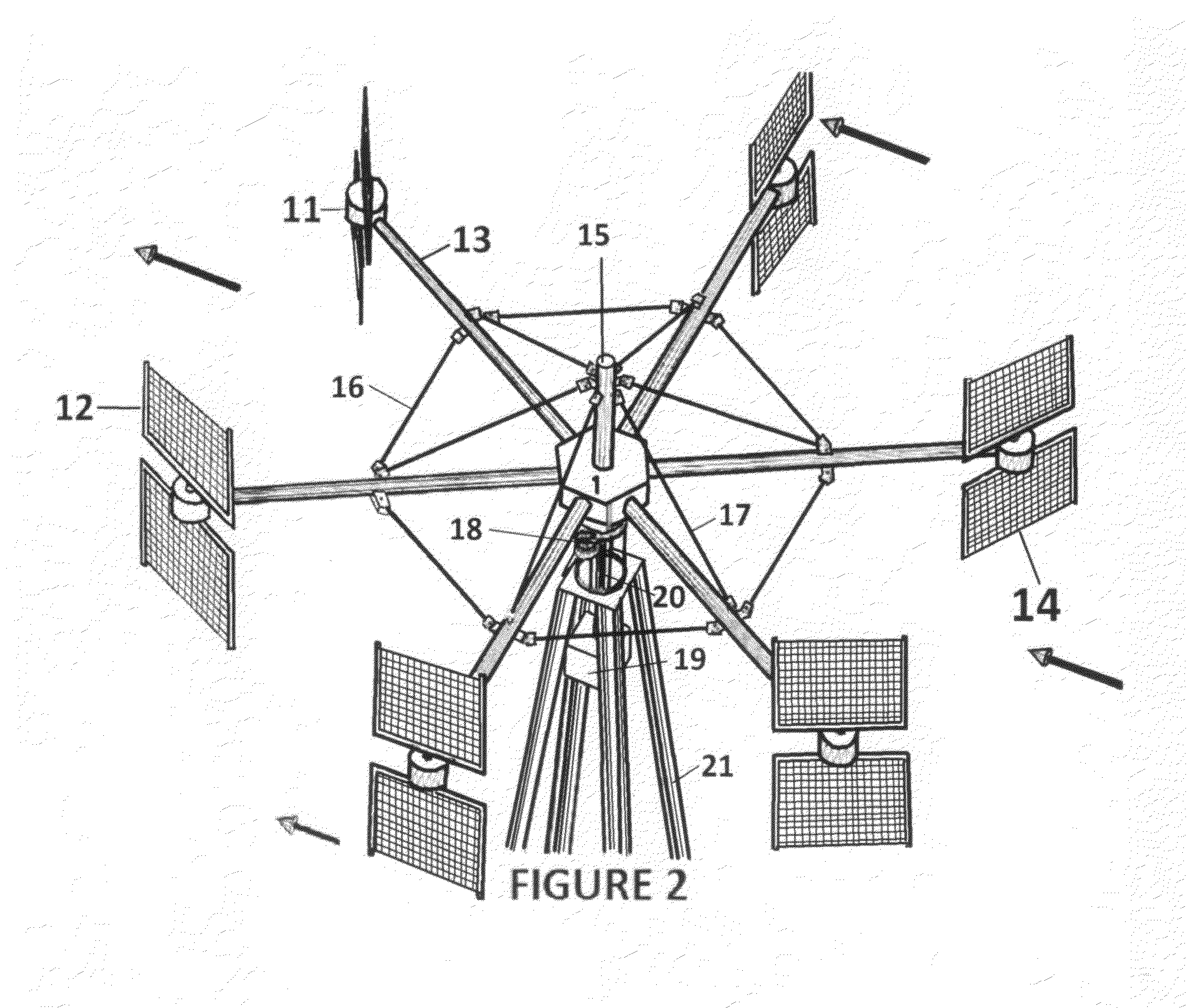
Burrell compound axial windmill

a windmill and compound technology, applied in the direction of electric generator control, renewable energy generation, greenhouse gas reduction, etc., to achieve the effect of minimizing the danger of boating and other uses of the river or stream

Inactive Publication Date: 2012-03-15
BURRELL LEO LEROY
View PDF13 Cites 18 Cited by
  • Summary
  • Abstract
  • Description
  • Claims
  • Application Information

AI Technical Summary

Benefits of technology

[0019]The BURRELL COMPOUND VERTICAL AXIS WINDMILL sails actually contribute to the power on the lee or quarter side of the mill. There are no losses of a returning sail such as are experienced with ordinary vertical axis windmills. When we first designed it, we used airfoil that keeps an airplane aloft to contribute power to the mill in the critical leeward to windward half of the rotation. We still have the technology to warp the two-faced sails so as to create airfoil, but further testing is needed. The sails of this invention face fully into the wind in the windward direction, and contribute variously as a tacking sailboat does—developing more force than a spinnaker driving downwind. The thrust developed when the sails of this invention are disposed quarterly with the wind and quarterly into the wind actually contribute more to the mill's velocity than when they face the wind. The wind attacking the sails progressively from the windward quarter through the windward alignments is warped in its direction such that it drives more forcefully against the sails in the leeward quarter alignment. The BURRELL pattern COMPOUND WINDMILL can be mounted: on a pole in a person's backyard; on a stout house roof, or in the median between roadways. And in its preferred embodiment it will be positioned as 100 kw or larger units at every rest area on every Interstate highway in America; in rural areas of India, China, Africa, and on every island of every ocean around the globe. As the world moves toward electric cars it will be a comfort to know a person is close to public facilities to recharge their car when they are traveling. People will have these windmills installed near their homes to provide 10 kw of power that is more than enough to provide for their needs, and they will share with neighbors or sell their exc

Problems solved by technology

LOOKING FORWARD, since the giant Propeller Windmills have their place on hills where the wind sweeps upward—but they are limited to that application, it will appear obvious to the casual observer that only a vert

Method used


Image

  • Burrell compound axial windmill
  • Burrell compound axial windmill
  • Burrell compound axial windmill

Examples


Embodiment Construction

[0030]We live in an age that is forced to deal with the possibility of terrorist attack by people with a cause; people with a grudge; people who are sick; people who by rapacity suppose they can impose their will on their neighbors. Terrorists tend to choose Monuments to destroy: Power Plants; Federal Buildings; Shrines, Trains, Airplanes, etc. It is well known that President Theodore didn't travel all the way to Africa to hunt mice. There would be no bragging rights in such a trophy. Our great Interstate Roadway System is a National Defense strategy that gives us mobility in time of adversity. When we replace all the coal, gas, and nuclear fired Power Plants with a profusion of small, medium and large Wind Powered Electric Generating stations the incentive to destroy a single Power Plant so as to create confusion and panic that target is removed. The Burrell Compound Vertical Axis Windmill in all its embodiments from single dwelling units of 1 Kw or less to large commercial units o...


PUM


Abstract

A plurality of sail assemblies rotating on their axes rotate about the axis of the windmill hub to rotate a drive shaft. The drive shaft powers a generator, machine, pump, grind-stone or other load the mill is designed to operate. Fabric, metal, or plastic sails are fitted to the frame arms of the sail assembly such that they are releasable under upset conditions such as hurricane or tornado wind velocities or other catastrophic inclusion. In the preferred embodiment of the invention drive shafts housed in tubular metal, plastic, or fiberglass connect the gears of the hub to helical or bevel type right angle gearboxes that rotate the sails at a rate of one time for each two times the hub rotates. A second embodiment of the mill has sprockets at the sail assemblies which drive a sprocket at the hub of the mill. The sprockets are rotated one time for each revolution of the hub sprocket via a roller chain. And the sail assemblies rotate in the same direction as the rotation of the hub sprocket. Other embodiments of the construction of the Burrell pattern Compound Windmill are contemplated. One such embodiment of the mill is mounted in a stream or river, and power is transmitted upward to a platform where a generator or other equipment perform work. Another variation of construction substantially uses parts commonly found in scrapped automobiles—permitting inexpensive windmills in villages in third-world countries where commercial electrical power is either too expensive or not available. Constant Velocity (CV) joints, wheels, alternators, power steering pumps, etc. can be salvaged, and a mill can be designed by a technician trained in that discipline.

Description

REFERENCES[0001]U.S. Pat. No. 7,780,416 B2 * Aug. 24, 2010 Al-Azzawi . . . 416 / 111[0002]U.S. Pat. No. 1,286,853 A * December 1918 Weaver . . . 416 / 50[0003]U.S. Pat. No. 3,920,354 A * November 1975 Decker . . . 416 / 117[0004]U.S. Pat. No. 4,365,935 A * December 1982 Zukeran . . . 416 / 117[0005]U.S. Pat. No. 4,649,284 A * March 1987 Hsech-Pen . . . 290 / 55[0006]U.S. Pat. No. 7,413,404 B2 * Aug. 19, 2002 Chuy-Nan Chie . . . 416 / 17; 416 / 116; 416 / 132 B; 415 / 4.2[0007]U.S. Pat. No. 7,344,353 B2 * Mar. 18, 2008 Pertti H. Naskali, Angus MacLean, C. C. Gray, Lewis, Newall . . . 415 / 4.2; 415 / 71;[0008]U.S. D591,234 S * Apr. 28, 2009 Yuji Unno D13 / 115; D13 / 118, 122, 199[0009]U.S. Pat. No. 7,540,705 B2 * Jan. 2, 2009 Garry Emshey . . . 415 / 4.1; 415 / 4, 127; 416 / 198 R, 228, 197 R[0010]U.S. Pat. No. 7,618,237 B2 * Nov. 17, 2008 Brandon W. Lucas, Daniel W. Lucas . . . 416 / 119; 416 / 132 B; 416 / 140[0011]U.S. Pat. No. 7,632 / 069 B2 * Dec. 15, 2009 Gene Ryland Kelley . . . 416 / 80; 416 / 82; 416 / 83; 414.4.2[0012...

Claims


Application Information

Patent Timeline
IPC IPC(8): F03D9/00F03D7/02
CPCF03B17/067Y02E10/28Y02E10/74F03D3/068Y02E10/30Y02E10/20
Inventor BURRELL, LEO LEROY
Owner BURRELL LEO LEROY
Why Eureka
Try Eureka