Electronic control apparatus for a vehicle

Active Publication Date: 2012-03-15
DENSO CORP
View PDF1 Cites 25 Cited by
  • Summary
  • Abstract
  • Description
  • Claims
  • Application Information

AI Technical Summary

Benefits of technology

[0007]An embodiment provides an electronic control apparatus for a vehicle which improve

Problems solved by technology

Hence, the controlling CPU may perform an abnormal process for the controlled variables of th

Method used


Image

  • Electronic control apparatus for a vehicle
  • Electronic control apparatus for a vehicle
  • Electronic control apparatus for a vehicle

Examples


Example

[0018]In the first embodiment, an electronic control apparatus for a vehicle is applied to an electronic control unit of a hybrid electric vehicle.

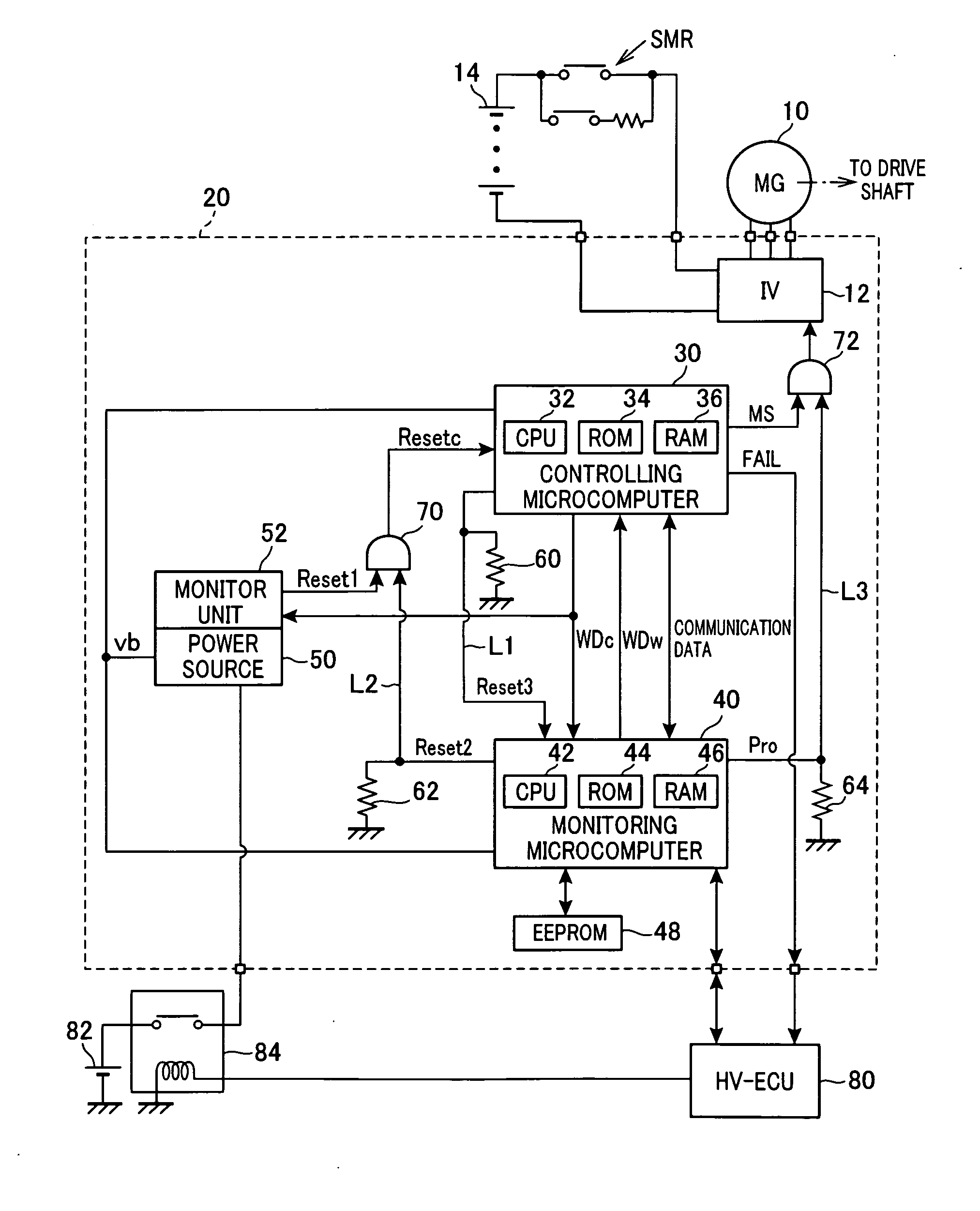
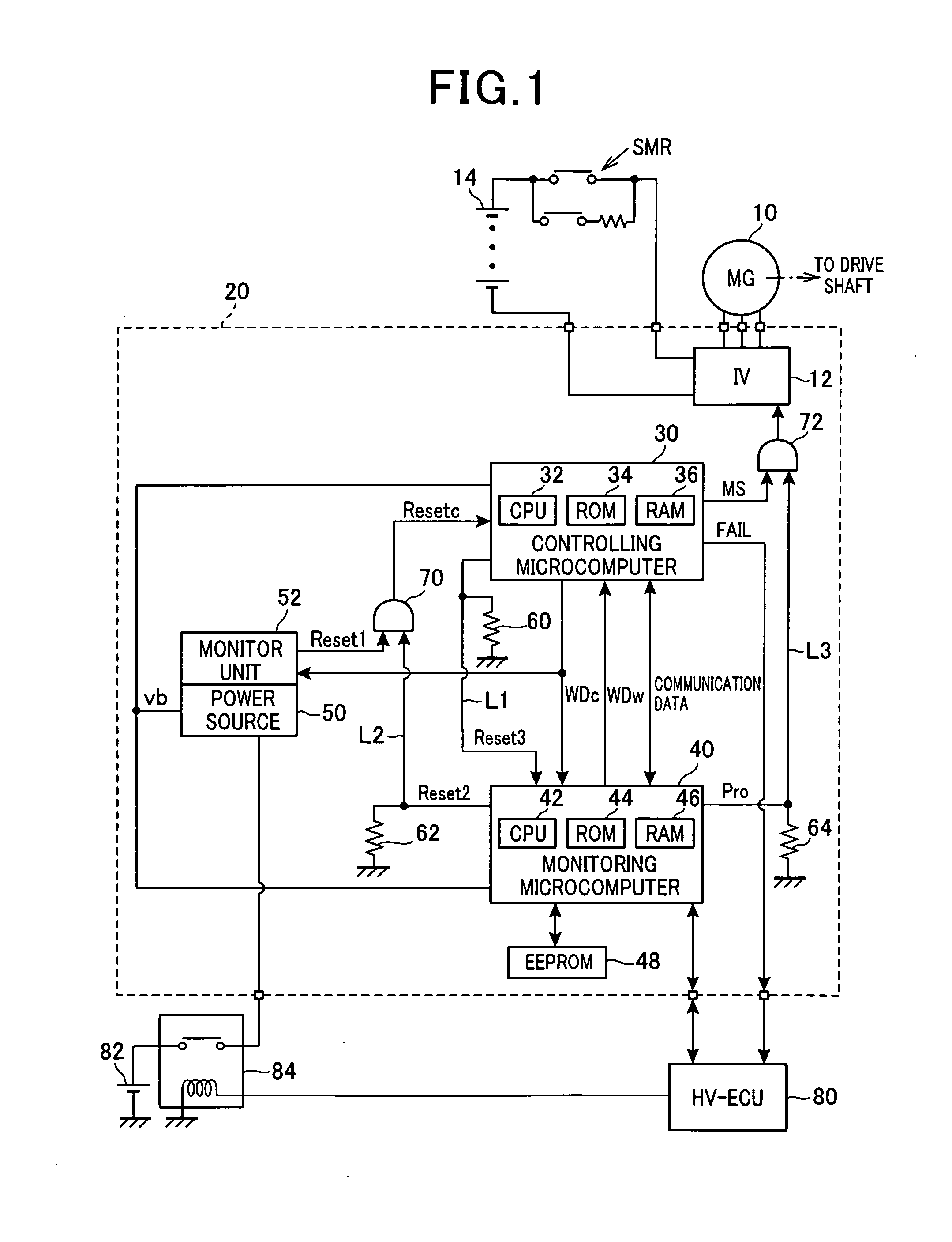
[0019]FIG. 1 is a diagram showing a system configuration according to the first embodiment.

[0020]A motor generator 10 is an in-vehicle traction unit which is mechanically connected with drive wheels. The motor generator 10 is connected to a high-voltage battery 14 via an inverter 12 formed in a motor generator electronic control unit (MGECU 20) and a relay SMR. The inverter 12 is a DC-AC conversion circuit which converts DC voltage of the high-voltage battery 14 into AC voltage.

[0021]The MGECU 20 includes an arithmetic processing unit (controlling microcomputer 30) which performs calculation for controlling controlled variables of the motor generator 10. The controlling microcomputer 30 includes a central processing unit (CPU 32), a ROM 34 and a RAM 36. The controlling microcomputer 30 corresponds to a software process means (unit) which ...

Example

Second Embodiment

[0072]In the second embodiment, configurations different from those of the first embodiment will be mainly described.

[0073]FIG. 6 is a diagram showing a system configuration according to the second embodiment, In FIG. 6, components corresponding to those shown in FIG. 1 are given the same numerals.

[0074]In the present embodiment, the monitor unit 52 separately outputs the reset signal Reset1 based on the watchdog signal WDc and the reset signal Resetb based on the voltage of the power source 50. The reset signal Resetb is outputted to not only the controlling microcomputer 30 but also the monitoring microcomputer 40. That is, the reset signal Resetb is inputted to the logic synthesis circuit 70 and a logic synthesis circuit 74. The logic synthesis circuit 74 outputs a logic synthesis signal of the reset signal Resetb and the reset signal Reset3 as a reset signal Resetw to the monitoring microcomputer 40.

[0075]In the present embodiment, the monitoring microcomputer 4...

Example

Third Embodiment

[0079]In the third embodiment, configurations different from those of the first embodiment will be mainly described.

[0080]FIG. 7 is a diagram showing a system configuration according to the third embodiment, In FIG. 7, components corresponding to those shown in FIG. 1 are given the same numerals.

[0081]In the present embodiment, a reset blocking switching element 76 is provided which opens and closes the signal line L1. The reset blocking switching element 76 can be operated by the monitoring microcomputer 40. This is the setting for avoiding a situation in which the monitoring microcomputer 40 is reset in conjunction with the reset of the controlling microcomputer 30 which is performed when the controlling microcomputer 30 is determined to be in an abnormal condition based on the watchdog signal WDc. That is, in the present embodiment, each signal outputted from the monitor unit 52 when the controlling microcomputer 30 is in an abnormal condition which is determined ...


PUM


Abstract

An electronic control apparatus for a vehicle, which operates a power conversion circuit connected to a rotating machine used as an in-vehicle traction unit to control controlled variables of the rotating machine, includes a controlling arithmetic processing unit which performs arithmetic processing to control the controlled variables of the rotating machine, and a monitoring arithmetic processing unit which monitors the controlling arithmetic processing unit. The monitoring arithmetic processing unit includes an on-monitoring prohibition unit which prohibits outputting an operation signal from the controlling arithmetic processing unit to the power conversion circuit until the controlling arithmetic processing unit is confirmed to be in a normal condition.

Description

CROSS-REFERENCE TO RELATED APPLICATION[0001]This application is based on and claims the benefit of priority from earlier Japanese Patent Application No. 2010-203970 filed Sep. 13, 2010, the description of which is incorporated herein by reference.BACKGROUND[0002]1. (Technical Field)[0003]The present invention relates to an electronic control apparatus for a vehicle which operates a power conversion circuit connected to a rotating machine used as an in-vehicle traction unit to control controlled variables of the rotating machine.[0004]2. (Related Art)[0005]An example of this type of electronic control apparatus is disclosed in JP-A-2003-214233. The electronic control apparatus includes a CPU for controlling an engine used as an in-vehicle traction unit (controlling CPU), and a CPU for monitoring the controlling CPU (monitoring CPU). When the monitoring CPU detects abnormality of the controlling CPU, a process is performed in which the controlling CPU is reset, and the operation there...

Claims


Application Information

Patent Timeline
IPC IPC(8): H02P6/12B60L50/16
CPCH02P23/0077H02P29/021Y02T10/7258B60L2240/80Y02T10/642B60L3/0084H02P29/0241B60L3/12B60L2210/40B60L2240/547Y02T10/70B60L50/16B60L50/51B60L58/21B60L58/40Y02T10/64Y02T10/72Y02T10/7072Y02T90/40
Inventor ITOU, AKITO
Owner DENSO CORP
Why Eureka
Try Eureka