Exposure apparatus, exposure method, and device manufacturing method
a technology of exposure apparatus and manufacturing method, which is applied in the direction of photomechanical treatment, printing, instruments, etc., can solve the problems of exposure defects and defective devices being produced, and achieve the effect of suppressing the occurrence of exposure defects and suppressing the occurrence of defective devices
- Summary
- Abstract
- Description
- Claims
- Application Information
AI Technical Summary
Benefits of technology
Problems solved by technology
Method used
Image

Examples
first embodiment
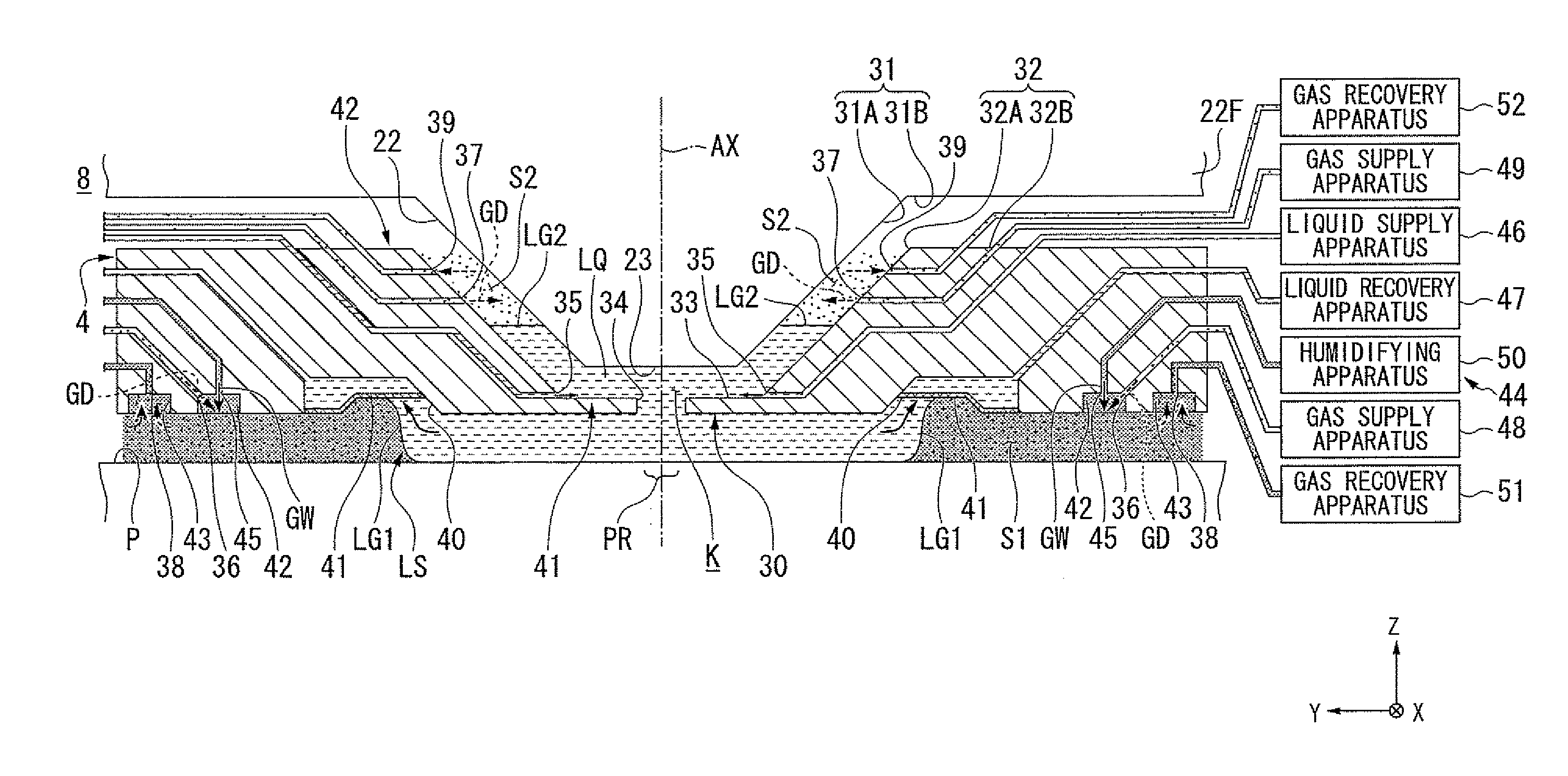
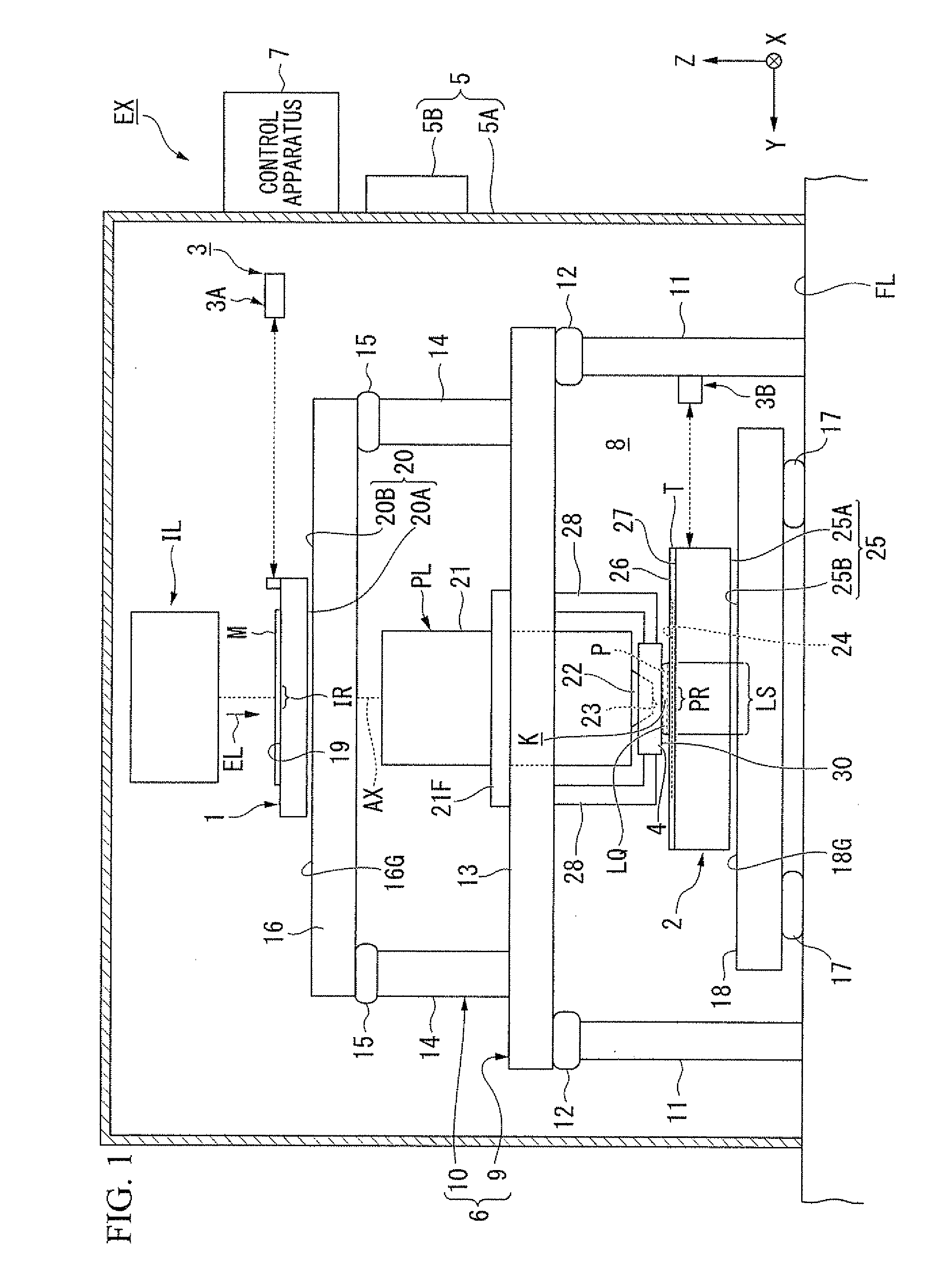
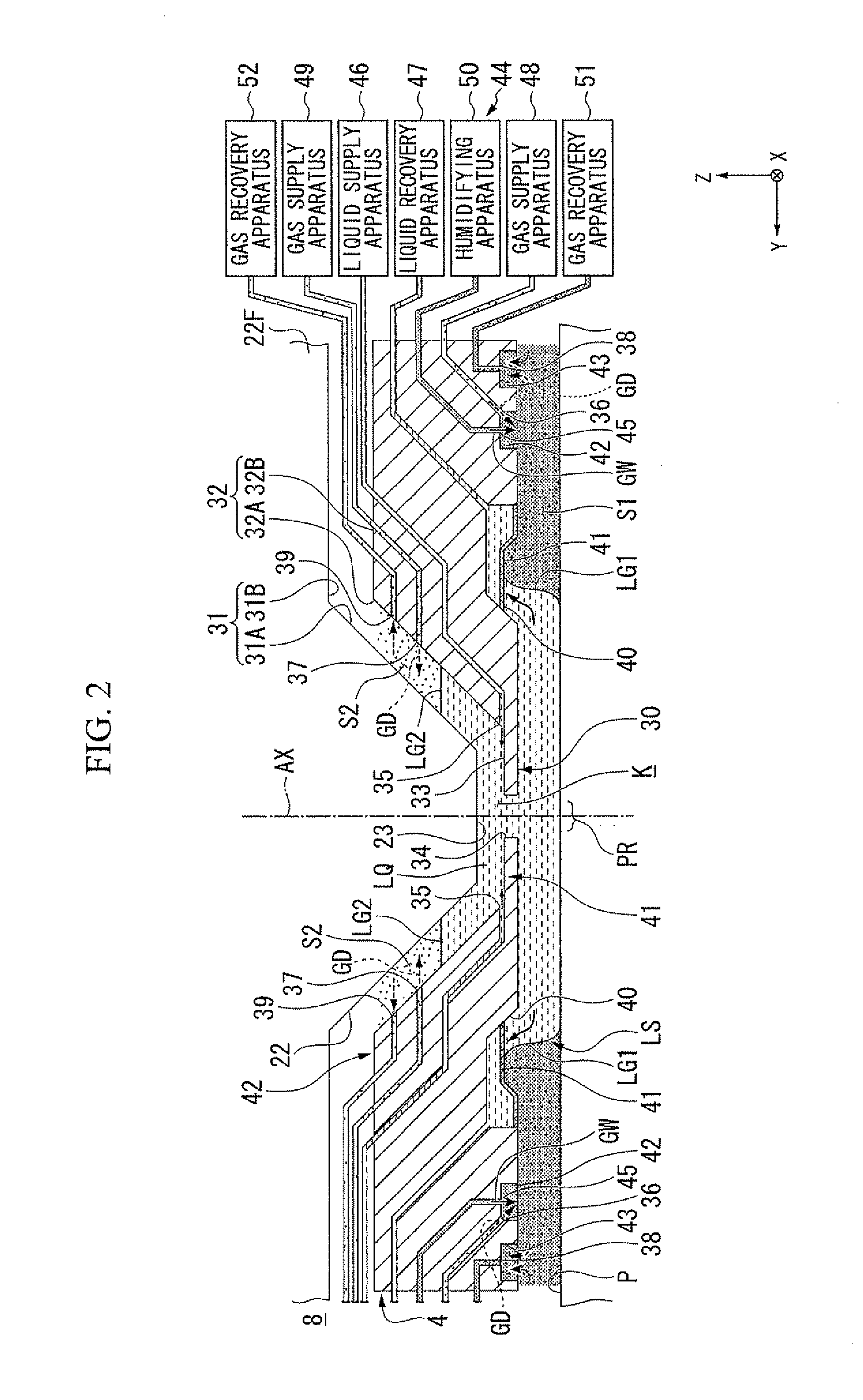
[0028]The first embodiment will be described. FIG. 1 is a schematic configuration view showing an example of an exposure apparatus EX according to the first embodiment. The exposure apparatus EX of the present embodiment is a liquid immersion exposure apparatus that exposes a substrate P with exposure light EL via a liquid LQ. In the present embodiment, a liquid immersion space LS is formed so that at least a part of the optical path of the exposure light EL is filled with the liquid LQ. The liquid immersion space LS is a portion (space or region) filled with the liquid LQ. The substrate P is exposed with the exposure light EL via the liquid LQ in the liquid immersion space LS. In the present embodiment, water (pure water) is used as the liquid LQ.
[0029]In FIG. 1, the exposure apparatus EX includes a mask stage 1 configured to be movable while holding a mask M, a substrate stage 2 configured to be movable while holding the substrate P, an interferometer system 3 that optically measu...
second embodiment
[0146]Next, the second embodiment will be described. In the following description, constituent elements which are the same as or similar to those of the above embodiment will be denoted by the same reference numerals, and description thereof will be simplified or omitted.
[0147]FIG. 4 is a view showing an example of a liquid immersion member 4B according to the second embodiment. The second embodiment is a modified example of the first embodiment. The characteristic part of the second embodiment different from the first embodiment described above is that concave portions 53 and 54 are formed on at least a part of an inner side surface 32A, a gas supply port 37B for supplying the gas GD and an air supply port 55B for supplying the steam GW are disposed on the inner surface of a concave portion 53 that defines the concave portion 53, and a gas recovery port 39B for recovering the gas GD and the steam GW is disposed on the inner surface of a concave portion 54 that defines the concave p...
third embodiment
[0154]Next, the third embodiment will be described. In the following description, constituent elements which are the same as or similar to those of the above embodiments will be denoted by the same reference numerals, and description thereof will be simplified or omitted.
[0155]FIG. 5 is a view showing an example of a liquid immersion member 4C according to the third embodiment. The third embodiment is a modified example of the first embodiment. The characteristic part of the third embodiment different from the first embodiment described above is that a gas supply port 36C, an air supply port 45C, and a gas recovery port 38C are disposed in at least a part of the circumference of the optical path K of the exposure light EL and on a holding member 56 disposed on the outer side of the liquid immersion member 4C in the radiation direction in relation to the optical axis AX.
[0156]In the present embodiment, the holding member 56 is an annular member disposed around the liquid immersion me...
PUM
 Abstract
Description
Claims
Application Information
 - R&D
- Intellectual Property
- Life Sciences
- Materials
- Tech Scout
- Unparalleled Data Quality
- Higher Quality Content
- 60% Fewer Hallucinations
Browse by: Latest US Patents, China's latest patents, Technical Efficacy Thesaurus, Application Domain, Technology Topic, Popular Technical Reports.
© 2025 PatSnap. All rights reserved.Legal|Privacy policy|Modern Slavery Act Transparency Statement|Sitemap|About US| Contact US: help@patsnap.com