System and method for damping lc circuits in power conversion systems

a technology of power conversion system and lc circuit, which is applied in the field of lc circuits, can solve the problems of affecting the stability of power conversion control, unsatisfactory large amount of power consumed by the resistor, and the bulky lc filter

Active Publication Date: 2012-03-15
GENERAL ELECTRIC CO
View PDF5 Cites 58 Cited by
  • Summary
  • Abstract
  • Description
  • Claims
  • Application Information

AI Technical Summary

Benefits of technology

[0008]In accordance with one embodiment disclosed herein, a power conversion system comprises a power converter comprising a plurality of semiconductor power switches, an LC filter coupled between an output of the power converter and an electric grid, and a power conversion control system. The LC filter comprises an inductor coupled in series to the electric grid, and a capacitor. The LC filter and the grid result in an equivalent LC circuit comprising an impedance of the LC filter and an impedance of the electric grid. The power conversion control system comprises a damper and a converter controller. The damper receives an LC filter signal and an equivalent LC circuit impedance signal, and generates a damping signal. The converter controller receives a current or voltage reference signal, a current or voltage command signal, and the damping signal to generate control signals for driving switching operations of the semiconduc...

Problems solved by technology

Drawbacks to the resistor embodiment are that an undesirably large amount of power is consumed by the resistor and that the LC filter becomes more bulky because the resistor occ...

Method used


Image

  • System and method for damping lc circuits in power conversion systems
  • System and method for damping lc circuits in power conversion systems
  • System and method for damping lc circuits in power conversion systems

Examples


Embodiment Construction

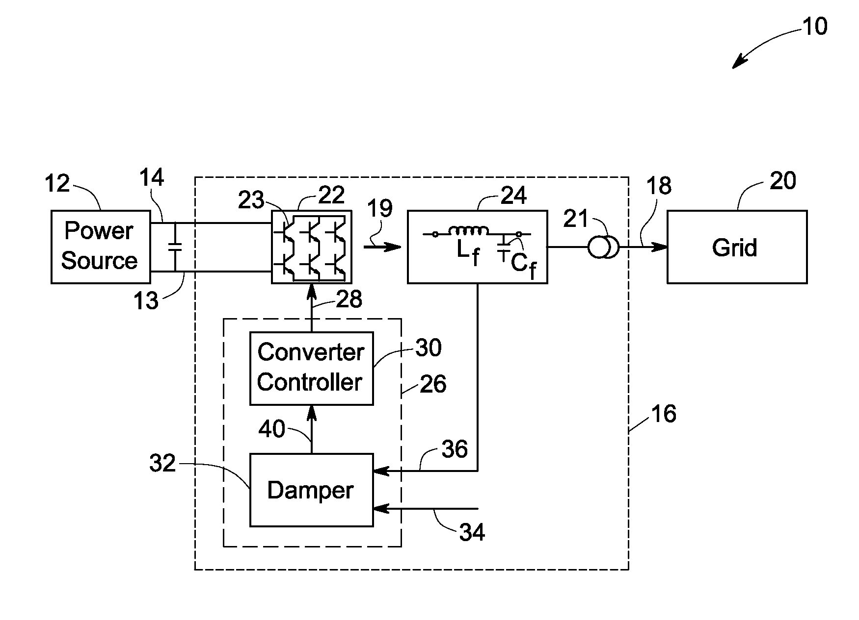
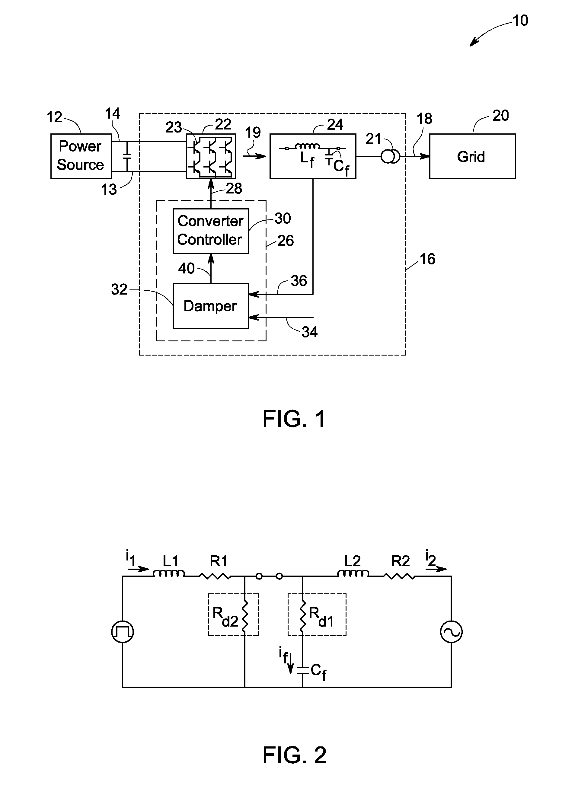
[0023]Embodiments of the invention relate to damping an LC circuit between a power converter and an electric grid. As used herein after, “LC circuit” refers to any equivalent circuit comprising capacitive and inductance components, and “LC filter” comprises any filter comprising capacitive and inductance components. In certain embodiments of the invention, the LC circuit comprises impedances of an LC filter comprising capacitive and inductive components, equivalent impedances of transmission lines and other electronic components between the converter and the grid, and an equivalent impedance of the grid. A damper receives estimated or measured equivalent LC circuit impedance signals and generates damping signals according to the estimated or measured equivalent LC circuit impedance signals. A converter controller uses the damping signals to control the converter.

[0024]Referring to FIG. 1, a power generation system 10 comprises a power source 12. In one embodiment, as shown, power so...


PUM


Abstract

A power conversion system comprises a power converter comprising a plurality of semiconductor power switches, an LC filter coupled between an output of the power converter and an electric grid, and a power conversion control system. The LC filter comprises an inductor coupled in series to the electric grid, and a capacitor. The LC filter and the grid result in an equivalent LC circuit comprising an impedance of the LC filter and an impedance of the electric grid. The power conversion control system comprises a damper and a converter controller. The damper receives an LC filter signal and an equivalent LC circuit impedance signal and generates a damping signal. The converter controller receives a current or voltage reference signal, a current or voltage command signal, and the damping signal to generate control signals for driving switching operations of the semiconductor power switches.

Description

BACKGROUND[0001]The invention relates generally to LC circuits and, more specifically, to a method and apparatus for damping of an LC circuit between a power converter and an electric grid.[0002]Renewable power generation systems include power sources such as solar panels or wind turbines, for example, and power converters for converting power from the power sources into power having an alternating current with controlled amplitude and frequency. It is desirable that the alternating current supplied to an electric grid be synchronous with the grid voltage or current and that harmonic components are minimized. Some power systems use LC filters to minimize high frequency harmonics.[0003]A typical LC filter includes inductors and capacitors. LC filter resonance is defined as the condition when the inductive reactance and capacitive reactance of the LC filter are of equal magnitude. The frequency at which resonance occurs is defined as the resonant frequency. Mathematically, the resonan...

Claims


Application Information

Patent Timeline
IPC IPC(8): H02M1/12
CPCH02M1/12H02M7/48Y02E10/763H02J3/386Y02E10/563H02J3/383H02J2300/28H02J2300/24H02J3/381Y02E10/56Y02E10/76H02J3/44
Inventor GONG, MAOZHONGTAN, ZHUOHUIYUAN, XIAOMINGWU, XUEQIN
Owner GENERAL ELECTRIC CO
Why Eureka
Try Eureka