Dual-cooled fuel rod's spacer grids with upper and lower cross-wavy-shape dimple

a dual-cooled fuel rod and spacer grid technology, applied in nuclear engineering, greenhouse gas reduction, nuclear elements, etc., can solve the problems of reducing the temperature of the fuel rod locally, and reducing the output of nuclear fuel, so as to reduce the pressure loss or transverse translation, reduce the vibration of the dual-cooled fuel rod, and the cross-sectional shape is simpl

Active Publication Date: 2012-03-15
KOREA ATOMIC ENERGY RES INST +1
View PDF6 Cites 5 Cited by
  • Summary
  • Abstract
  • Description
  • Claims
  • Application Information

AI Technical Summary

Benefits of technology

[0031]According to the present invention, the dual-cooled fuel rod's spacer grid effectively supports the dual-cooled fuel rods arranged at very narrow intervals in a firm structure, reduces pressure loss or transverse translation in a simple cross-sectional shape, and reduces vibration of the dual-cooled fuel rods that occurs over the lifespan of th

Problems solved by technology

As a result, heat generated from the fuel rods is not effectively transmitted to the coolant, thereby causing the phenomenon of the temperature of the fuel rod being locally increased.
Accordingly, there is a high possibility of generating a departure from nucleate boiling (DNB) that is a major cause of reduced output of nuclear fuel.
The turbulent flow of the coolant around the fuel rods becomes a major cause of flow-induced vibration of the fuel rods.
Thus, the fuel rod is gradually damaged, i.e. fretting damage is caused to the fuel rod.
The flow-induced vibration of the nuclear fuel caused by the high-speed flow of the coolant in the reactor core during its operation occurs over the life span of the nuclear fuel, so that the fretting damage caused by the relative motion occurs at the support points of the

Method used


Image

  • Dual-cooled fuel rod's spacer grids with upper and lower cross-wavy-shape dimple
  • Dual-cooled fuel rod's spacer grids with upper and lower cross-wavy-shape dimple
  • Dual-cooled fuel rod's spacer grids with upper and lower cross-wavy-shape dimple

Examples


Embodiment Construction

[0043]Reference will now be made in greater detail to exemplary embodiments of the invention with reference to the accompanying drawings.

[0044]The present invention is characterized by being configured so that a blocking area of a flow passage through which a coolant flows is reduced and dual-cooled fuel rods are supported, and by reducing a turbulent flow of the coolant as well as vibrations of the dual-cooled fuel rods, thereby reducing fretting damage done to the dual-cooled fuel rods.

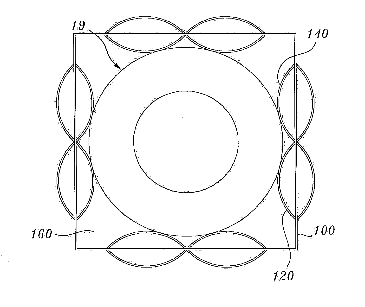
[0045]FIG. 8 is a perspective view illustrating a unit grid strap of a dual-cooled fuel rod's spacer grid with upper and lower cross-wavy-shape dimples according to an exemplary embodiment of the present invention. FIG. 9 is a top-down view illustrating the unit grid strap of FIG. 8. FIG. 10 is a top-down view illustrating how the unit grid straps of FIG. 8 form a grid structure to support a dual-cooled fuel rod.

[0046]Referring to the figures, the dual-cooled fuel rod's spacer grid with upper and lo...


PUM


Abstract

A dual-cooled fuel rod's spacer grid with upper and lower dimples, including a blocking area of a flow passage that coolant flows through is reduced and dual-cooled fuel rods are supported, and reduces a turbulent flow of the coolant as well as vibrations of the dual-cooled fuel rods, thereby lessening fretting damage done to the rods. The spacer grid includes a plurality of unit grid straps, each of which includes a body disposed in a vertical direction, an upper dimple protruding from an upper portion of the body, and a lower dimple spaced apart from the upper dimple in a downward direction and protruding from a lower portion of the body. The unit grid straps form a grid structure that have inner grid holes into which the dual-cooled fuel rods are held, and the held dual-cooled fuel rods are each supported in four directions by the upper and lower dimples.

Description

BACKGROUND OF THE INVENTION[0001]1. Field of the Invention[0002]The present invention relates to spacer grids for dual-cooled fuel rods, and more particularly to spacer grids for dual-cooled fuel rods, the spacer grids having upper and lower cross-wavy-shape dimples, capable of improving support stability of dual-cooled fuel rods.[0003]2. Description of the Related Art[0004]FIG. 1 is a schematic perspective view showing a conventional fuel rod assembly. FIG. 2 is a schematic top-down cross-sectional view showing the conventional fuel rod assembly. FIG. 3 is a schematic top-down view showing a part of a spacer grid applied to the conventional fuel rod assembly. FIG. 4 is a schematic perspective view showing a part of a spacer grid applied to the conventional fuel rod assembly. FIG. 5 is a schematic perspective view showing a unit grid strap of the spacer grid supporting the conventional fuel rod assembly.[0005]As shown in the figures, the fuel rod assembly 10 is made up of fuel rods ...

Claims


Application Information

Patent Timeline
IPC IPC(8): G21C3/34
CPCG21C3/322Y02E30/38G21C3/3563G21C3/352Y02E30/30
Inventor SHIN, CHANG HWANLEE, KANG HEEOH, DONG-SEOKIN, WANG KEECHUN, TAE HYUNSONG, KUN WOO
Owner KOREA ATOMIC ENERGY RES INST
Why Eureka
Try Eureka