Acoustic apparatus

a technology of acoustic equipment and acoustic frequency, which is applied in the field of acoustic equipment, can solve the problems of increased possibility, noise generation from noise sources, and deterioration of the s/n ratio of a signal picked up by a microphone, and achieve the effect of accurate impulse respons

Active Publication Date: 2012-03-15
CANON KK
View PDF4 Cites 22 Cited by
  • Summary
  • Abstract
  • Description
  • Claims
  • Application Information

AI Technical Summary

Benefits of technology

[0018]The present invention provides an acoustic apparatus which can acquire an accurate impulse response by controlling the sound reproduction intervals of measurement signals, in accordance with peak frequencies of background noise, in impulse response measurement.
[0022]As described above, according to the present invention, controlling the sound reproduction intervals of measurement signals, in accordance with peak frequencies of background noise, in impulse response measurement can obtain an accurate impulse response by canceling out peak frequency components at the time of arithmetic mean operation.

Problems solved by technology

When measuring an impulse response in a room, the S / N ratio of a signal picked up by a microphone deteriorates because background noise always exists in the room.
These noise sources generate noise from driving unit (for example, the hard disk, fan, and the like of the personal computer) where electric energy is converted into mechanical motion.
This has increased the possibility that various peak frequency components of background noise will mix in the signal picked up by a microphone in accordance with the respective measurement places and measurement timings.
For this reason, besides being accustomed to such sound, it is difficult for the user to perceive them as noise.
This makes it difficult to take countermeasures such as eliminating a noise source in advance.
As described above, in practice, it is very likely that while peak frequency components as background noise will mix in picked-up signals actually acquired by an acoustic apparatus.
However, when an acoustic apparatus automatically generates a sound field correction filter, it is impossible to discriminate noise as peak frequency components of background noise on the f characteristic.
Applying such a filter to the original characteristics based on the interaction between the speaker and the room shown in FIG. 3C will lead to a deterioration in sound quality such as the sound loss of music.
That is, peak frequency components themselves are difficult to perceive by the user, but appear as a large peak on the f characteristic of a measured impulse response.
For this reason, using an improper sound field correction filter to correct such noise will make the user perceive the peak as a deterioration in sound quality.
This makes it impossible to secure a satisfactory S / N ratio for peak frequency components of background noise.
In addition, forcedly increasing a signal may cause clipping or distortion.
However, this processing does not measure background noise and is not specialized for a specific peak frequency.

Method used


Image

  • Acoustic apparatus
  • Acoustic apparatus
  • Acoustic apparatus

Examples


first embodiment

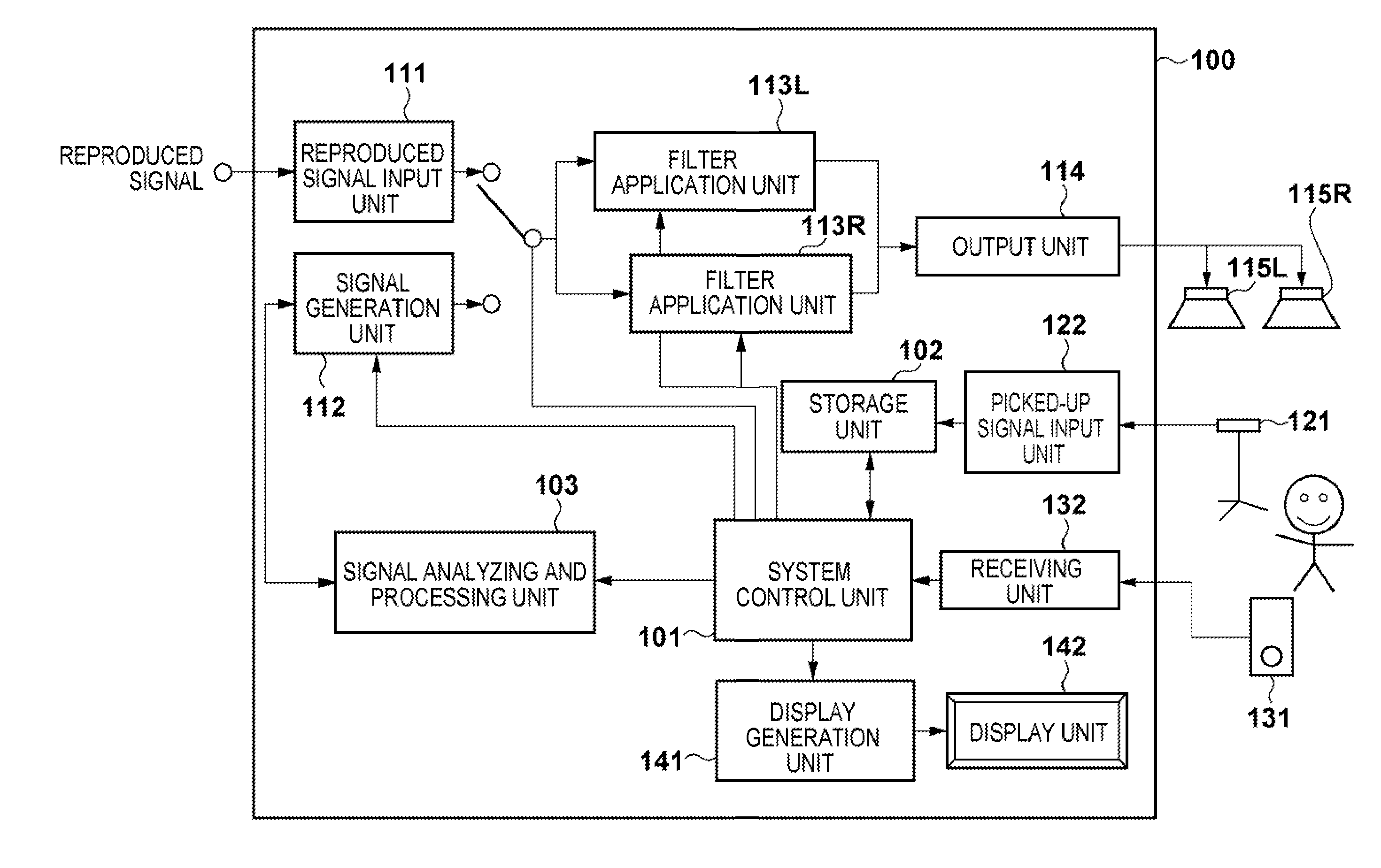
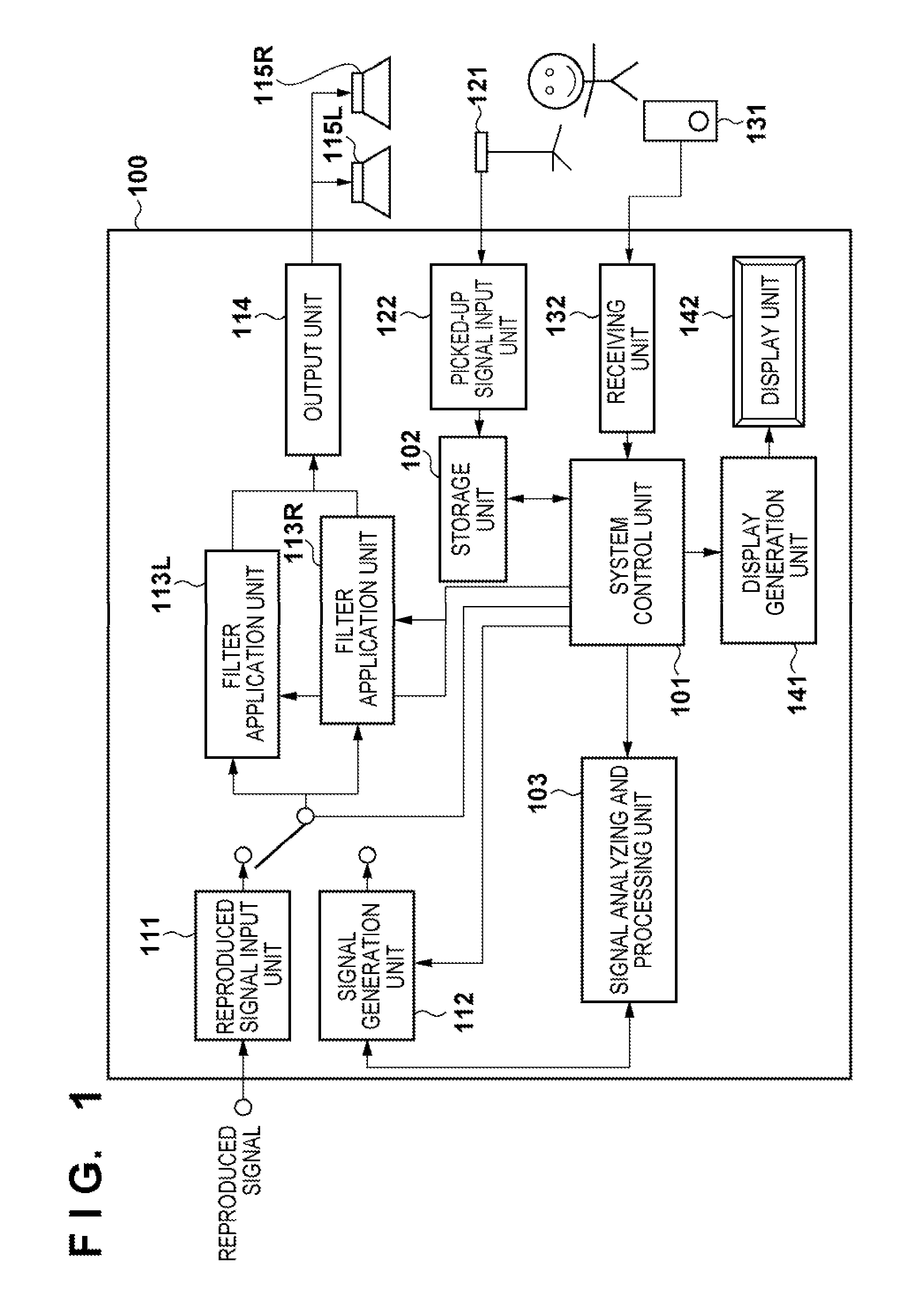
[0040]FIG. 1 is a block diagram showing the arrangement of an acoustic apparatus according to the first embodiment of the present invention.

[0041]The acoustic apparatus shown in FIG. 1 includes a controller 100 as a main unit. The controller 100 includes a system control unit 101 which performs overall control of the apparatus, a storage unit 102 which stores various data, and a signal analyzing and processing unit 103 which analyzes and processes a signal. Elements that implement the function of a reproduction system include a reproduced signal input unit 111, a signal generation unit 112, filter application units 113L and 113R, an output unit 114, and speakers 115L and 115R as sound sources. Elements which implement the function of a sound pickup system include a microphone 121 and a sound pick-up signal input unit 122.

[0042]As elements for accepting command inputs from the user, this apparatus further includes a remote controller 131 and a receiving unit 132. Elements for present...

second embodiment

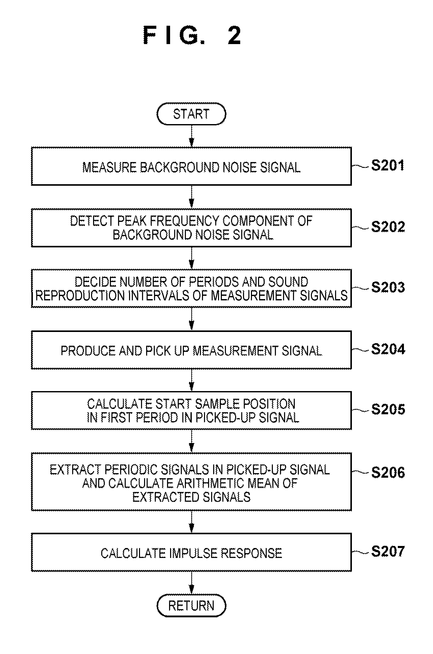
[0093]In the first embodiment described above, since n independent sound reproduction intervals tk (k=1 to n) are introduced for n peak frequencies fk (k=1 to n), measurement signals in 2n periods are required.

[0094]The second embodiment searches for sound reproduction intervals that allow to collectively process a plurality of peak frequencies as one processing target. That is, this embodiment regards n peak frequencies as m processing targets which are smaller in number than the n peak frequencies, and introduces m independent sound reproduction intervals to suppress the number of periods of measurement signals to 2m, thereby shortening the measurement time.

[0095]The basic principle of the present invention is that when calculating arithmetic mean of two signals, the interval between the two signals is controlled to cancel out a target peak frequency component of a background noise signal completely in theory. Consider a theoretically maximum amplitude A as an evaluation index for...


PUM


Abstract

Measurement signals for calculating acoustic characteristics of the acoustic space are reproduced in a plurality of periods at sound reproduction intervals. A picked-up signal is acquired by picking up a reproduced signal. The picked-up signal is divided for each period, and the acoustic characteristics of the acoustic space are calculated from an arithmetic unit of the divided periodic signals and the measurement signal. Before sound reproduction, a background noise signal in the acoustic space is measured, and a peak frequency component of a frequency characteristic of the background noise signal is detected. The number of periods and sound reproduction intervals of measurement signals to be reproduced are controlled so as to cancel out a detected peak frequency component at the time of calculating arithmetic unit.

Description

BACKGROUND OF THE INVENTION[0001]1. Field of the Invention[0002]The present invention relates to an acoustic apparatus which measures acoustic characteristics in an acoustic space, a method of controlling the apparatus, and a program.[0003]2. Description of the Related Art[0004]The impulse response between a sound source and a sound receiving point in an acoustic space such as a room or hall includes important information concerning the acoustic characteristics of the space. For example, the user of an acoustic apparatus can obtain an acoustic effect as if he / she were listening to music in a given famous hall by storing the impulse response measured in the hall in the storage unit of the apparatus and performing filtering processing by applying the impulse response to a music signal to be reproduced. In some cases, the user may place a microphone at a listening point in a room where he / she listens to music, and reproduce a measurement sound signal from each speaker to measure the im...

Claims


Application Information

Patent Timeline
Patent Type & Authority Applications(United States)
IPC IPC(8): H04R29/00
CPCH04S7/305G01H7/00
Inventor TAWADA, NORIAKI
Owner CANON KK
Why Eureka
Try Eureka