
Passive optical network system

a technology of optical communication system and optical communication device, which is applied in the direction of multiplex communication, star/tree network, transmission monitoring, etc., can solve the problems of failure of the receiving device of the onus close to the ground, the sensitivity of the light receiving device exceeds the allowable range, and the failure of the light receiving device. to achieve the effect of extending the communication distance between the olt and the onus

Inactive Publication Date: 2012-03-15
HITACHI LTD
View PDF4 Cites 43 Cited by
  • Summary
  • Abstract
  • Description
  • Claims
  • Application Information

AI Technical Summary

Benefits of technology

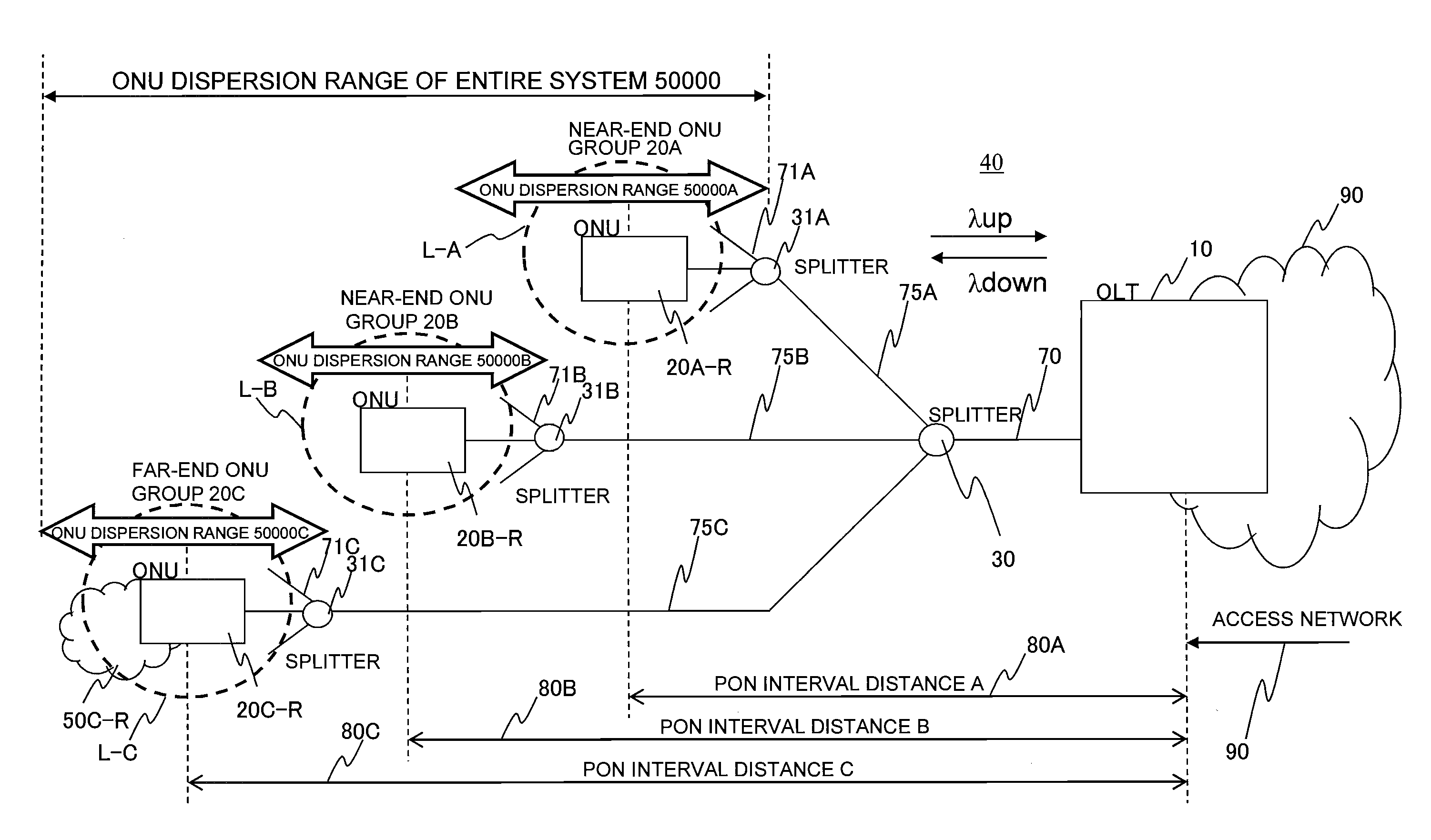
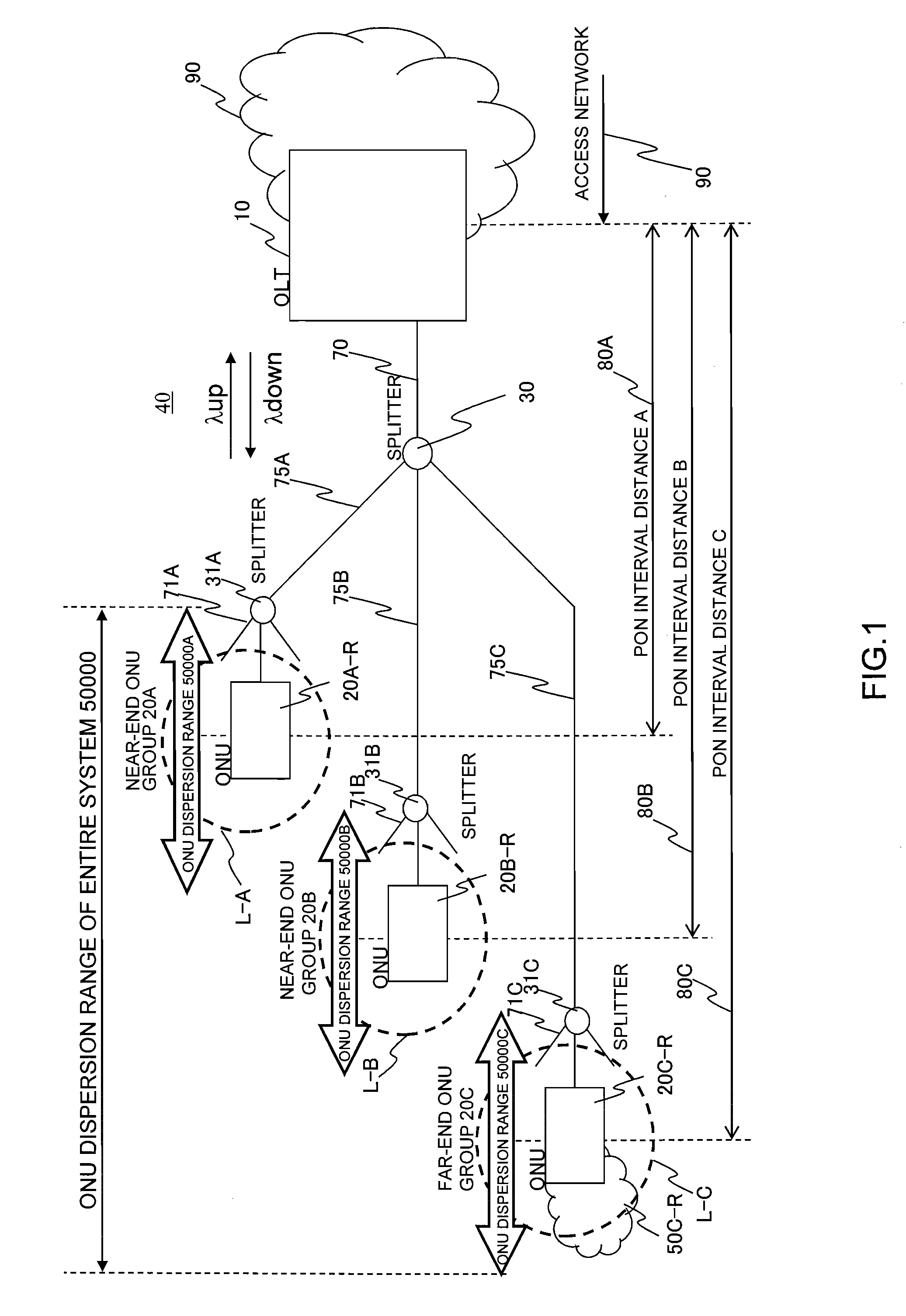
[0011]In order to increase the number of users accommodated in the PON, a method of enlarging an ONU distribution (distribution of a distance between OLT and ONUs; hereinafter referred to as “difference distance of ONUs”) connected to the OLT installed in a station is effective. When the ONU difference distance is increased, if a downstream signal transmitted from the OLT to the ONUs is received by the ONUs, there arises such a problem that a received light intensity or an S / N ratio is largely different between the closest ONU and the farthest ONU when viewed from the OLT, which may exceed an allowable range of a light receiving device sensitivity. This is caused because difference in the optical fiber distances to the individual ONUs by which the optical signal passes is larger than that in the related art. The number of splitters through which the optical signal passes from the OLT to the ONUs is different depending on the PON configuration (in general, the number of passed splitters is more increased as the ONUs are farther from the OLT), and an light intensity difference of the downstream signals received by the respective ONUs is further increased.
[0014]An object of the present invention is to provide a downstream signal transmitting method in which even if an optical amplifier is introduced into the PON to extend a communication distance between the OLT and the ONUs or to increase the number of ONUs, in the ONUS the respective performances of which are equal to each other, a failure of optical receivers attributable to an excessive received light intensity, or a reception failure caused by the deterioration of the optical signal are prevented from occurring, and the downstream signal from the OLT is received by all of the ONUs to maximize a communication traffic per ONU. Another object of the present invention is to provide a PON system and a downstream signal control method in the PON, which can suppress the above problems without largely changing the functions provided in the related-art PON.
[0028]According to the present invention, the communication distance between the OLT and the ONUs can be extended.

Problems solved by technology

When the ONU difference distance is increased, if a downstream signal transmitted from the OLT to the ONUs is received by the ONUs, there arises such a problem that a received light intensity or an S / N ratio is largely different between the closest ONU and the farthest ONU when viewed from the OLT, which may exceed an allowable range of a light receiving device sensitivity.
However, it is difficult to improve the performance of the light receiving device without increasing the price.
Conversely, when the optical signal transmitted to the ONU remotely situated is received by the ONU closely situated, there is a possibility that the receiving device of the ONU closely situated fails.
That is, even if the distance between the OLT and the ONUs is identical with that in the existing PON, a difference in the transmission characteristic of the optical fiber caused by the difference in the bit rate leads to an unignorable difference in the light intensity received by the ONU side.
Also, due to the feature of the PON that a communication bandwidth is shared by the entire ONUs with an increase in the number of ONUs, there is disadvantageous in that the bandwidths assigned to the individual ONUs are decreased.

Method used


Image

  • Passive optical network system
  • Passive optical network system
  • Passive optical network system

Examples


Embodiment Construction

[0053]Hereinafter, a description will be given of embodiments of the present invention in detail with reference to the accompanying drawings. Substantially the same parts are denoted by identical reference numerals, and their repetitive description will be omitted. Also, the configuration and operation of a PON according to the embodiments will be described as the configuration and operation of the GPON specified in ITU-T Recommendation G.984.3. However, the PON of the embodiments is not limited to the GPON.

[0054]Referring to FIG. 1, a PON system according to this embodiment will be described. Referring to FIG. 1, a PON system 40 includes an OLT 10, an ONU group 20A, an ONU group 20B, and an ONU group 20C. A concentrated optical fiber 70 connects the OLT 10 to a splitter 30. A first branch optical fiber 75 connects the splitter 30 to a branch splitter 31. A second branch optical fiber 71 connects the branch splitter 31 to an ONU 20.

[0055]The ONU group 20A is an ONU group at a neares...


PUM


Abstract

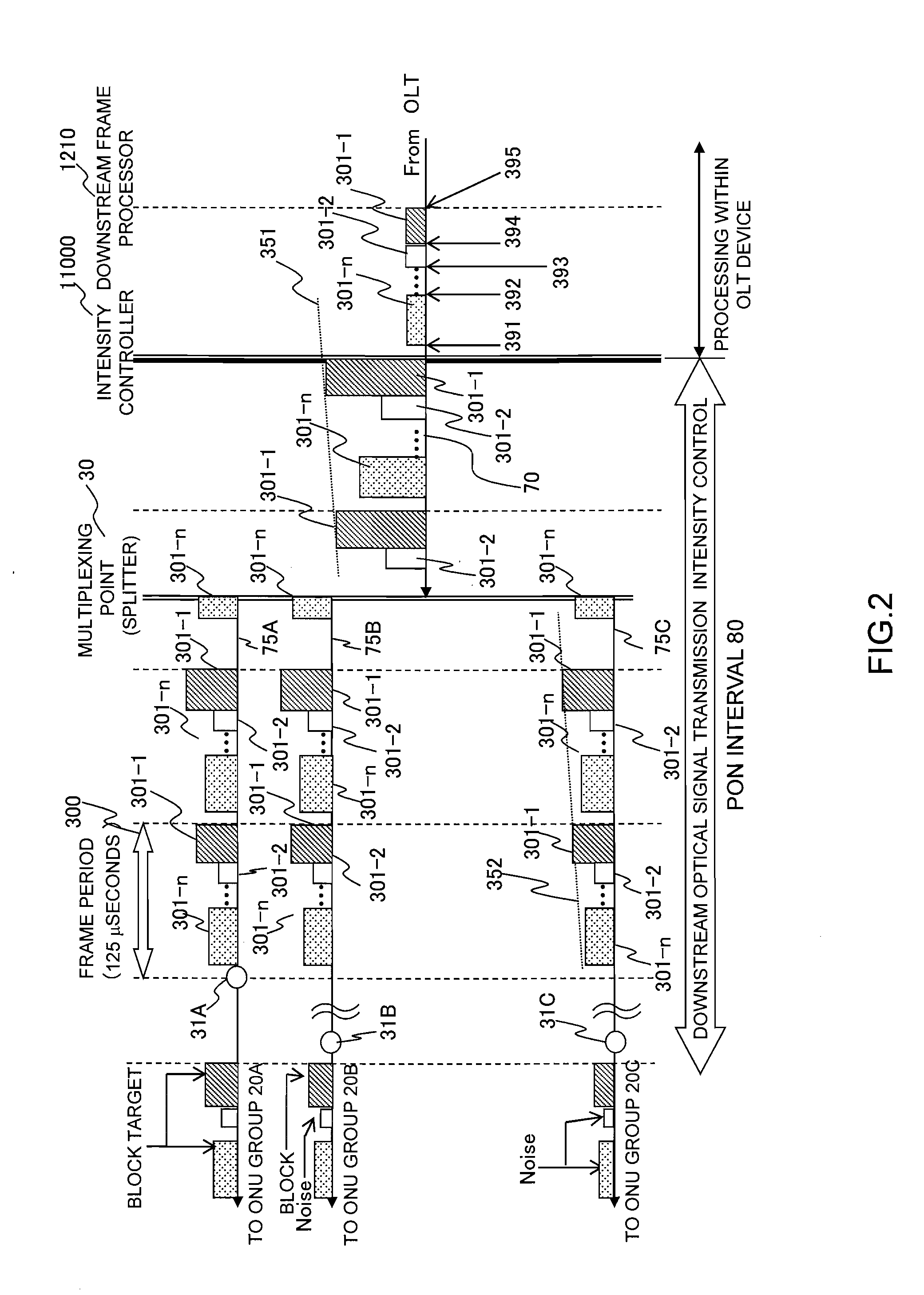
When an ONU accommodating range is enlarged, and ONUs shorter and ONUs longer in a communication path to an OLT are accommodated in a PON at the same time, there is a need to change a light intensity at the time of transmitting a downstream signal in order that both of the ONUs receive a downstream signal from the OLT. When a near-end ONU receives a signal having a light intensity necessary to communicate between the OLT and a far-end ONU, there arises such a problem that the light intensity is as high as an ONU receiver fails. In order to eliminate the ONU failure of the above problem, prior to transmission of the downstream signal, a downstream signal transmission schedule (downstream light intensity map) is notified to all of the ONUs. An optical transceiver of the OLT has a function of adjusting an output light intensity, and adjusts the light intensity to values receivable by the individual ONUs when the signal arrives at the respective ONUs according to route distances to the respective ONUs.

Description

CLAIM OF PRIORITY[0001]The present application claims priority from Japanese patent application JP 2010-203020 filed on Sep. 10, 2010, the content of which is hereby incorporated by reference into this application.BACKGROUND OF THE INVENTION[0002]1. Technical Field[0003]The present invention relates to a configuration and an operating method of an optical communication system in which plural subscriber devices share an optical transmission line, and a system extension such as an extension of a transmission distance or an increase in the number of subscribers in the system.[0004]2. Related Art[0005]A demand for communication using broadband has been increased, and an access line for users has increasingly undergone transition from an access technology based on a telephone line such as digital subscriber lines (DSL) to a large-capacity access line using optical fibers. At present, in the access line service, passive optical network (PON) systems have been frequently used from the view...

Claims


Application Information

Patent Timeline
IPC IPC(8): H04B10/08H04B10/12H04L12/44H04B10/07H04B10/27H04B10/272H04B10/293H04B10/564H04B10/572
CPCH04J3/1694H04J2203/0058H04Q2011/0079H04Q11/0067H04J2203/0066
Inventor NIIBE, MASAOMIZUTANI, MASAHIKO
Owner HITACHI LTD
Learn More