
Anastomotic devices and methods

a technology which is applied in the field of anastomosis and blood access devices and methods, can solve the problems of increasing the risk of bleeding and infection of patients in need of more immediate dialysis, increasing the risk of bleeding and infection of patients, and reducing the effect of vessel necrosis and pinching force of the vessel wall

Active Publication Date: 2012-03-15
WL GORE & ASSOC INC
View PDF2 Cites 116 Cited by
  • Summary
  • Abstract
  • Description
  • Claims
  • Application Information

AI Technical Summary

Benefits of technology

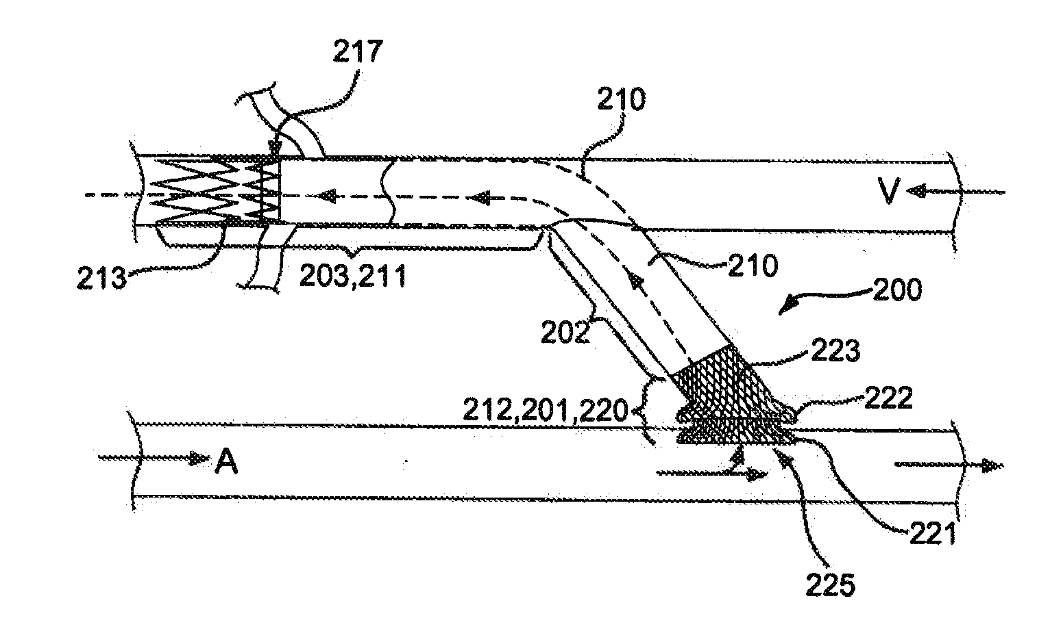
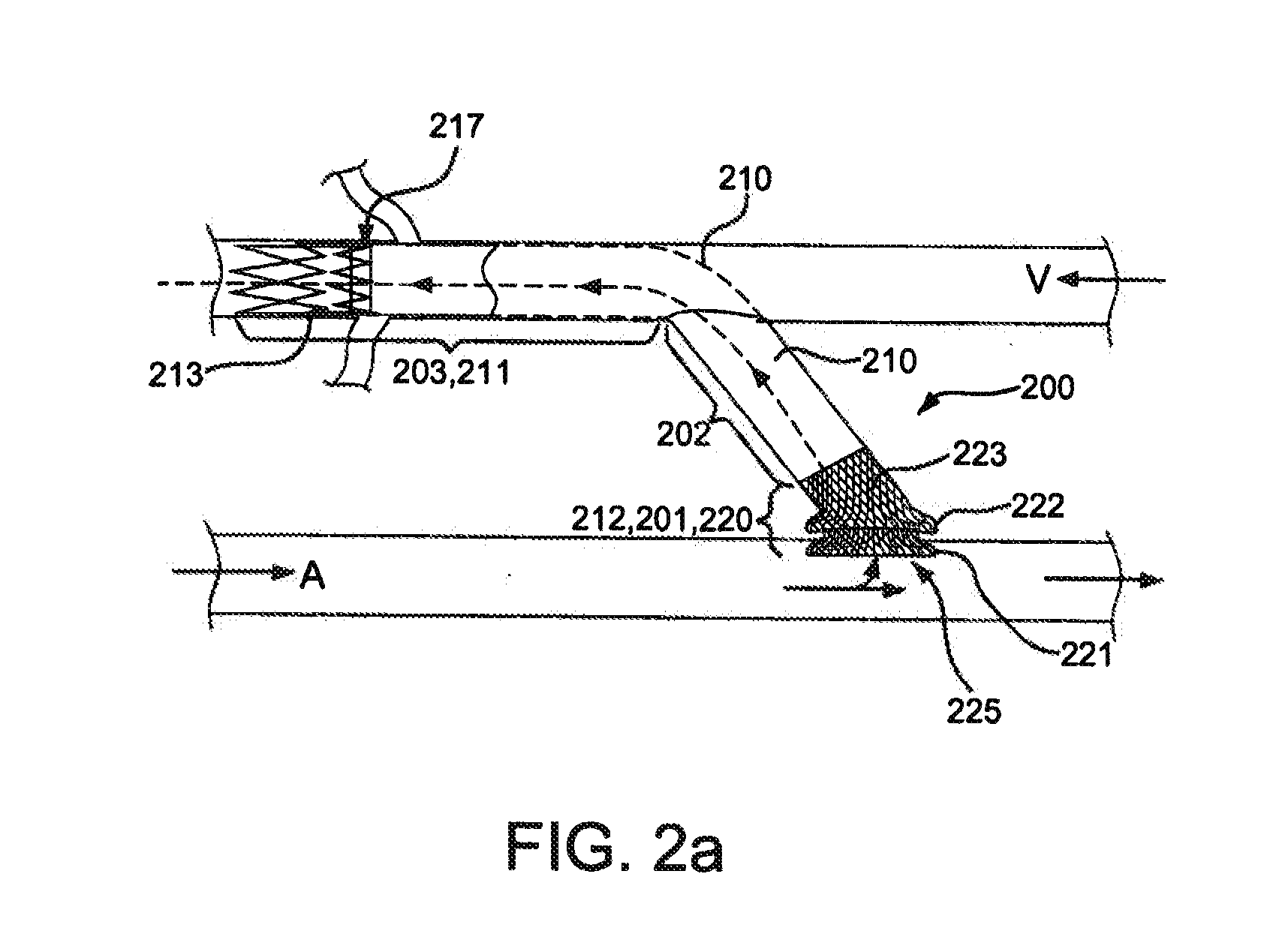
[0012]According to another aspect of the invention, a stent graft comprises a sidewall port device having dual flanges for coupling the stent graft to a surgically made aperture in a vascular wall or another stent device. According to another aspect of the invention, a stent graft includes a single flange for coupling a conduit through an aperture in a vascular wall and / or the wall of another stent device. A single flange extends generally radially outwardly from an end of the stent graft and resides in proximity to the luminal wall of vessel and / or stent device upon deployment. The single flange mechanically engages the luminal wall and may be held in place against the vessel wall by fluid pressure and / or an interference fit. The single flange portion reduces the effect of necrosis of the vessel by reducing the pinch force of the vessel wall.

Problems solved by technology

Failure to mature of new fistulas remains a major obstacle to increasing the proportion of dialysis patients with fistulas.
In addition, waiting for a fistula to mature exposes those patients in need of more immediate dialysis to increased risk, because a less-desirable temporary access device may be employed.
The use of a temporary catheter access exposes the patient to additional risk of bleeding and infection, as well as discomfort, and is associated with a 91% higher mortality rate compared to fistulas.
Moreover, some people are less than ideal candidates for a fistula.
For example, if the vascular system is greatly compromised, a fistula may not be attempted because the implantation may require an invasive surgical procedure that causes trauma to vessel walls and thus, is too risky for those with a weakened vasculature.
In addition, AV fistula may not be feasible in all patients due to anatomical considerations.

Method used


Image

  • Anastomotic devices and methods
  • Anastomotic devices and methods
  • Anastomotic devices and methods

Examples


Embodiment Construction

[0029]Persons skilled in the art will readily appreciate that various aspects of the present invention may be realized by any number of methods and apparatuses configured to perform the intended functions. Stated differently, other methods and apparatuses may be incorporated herein to perform the intended functions. It should also be noted that the accompanying drawing figures referred to herein are not all drawn to scale, but may be exaggerated to illustrate various aspects of the present invention, and in that regard, the drawing figures should not be construed as limiting.

[0030]Although the present invention may be described in connection with various principles and beliefs, the present invention should not be bound by theory. For example, the present invention is described herein in connection with anastomosis, such as vascular access fistula devices, in the context of hemodialysis in particular. However, the present invention may be applied toward any conduit connecting devices...


PUM


Abstract

Exemplary embodiments comprise AV fistulas and other anastomotic devices for creating new or reinforcing existing side-branch vessels, and / or bridging neighboring vessels together. An exemplary embodiment may comprise a sidewall port, such as a flanged sidewall port, and / or flow frame design, such as a partially bare, flexible stent or a whisk, for purposes of creating a transmural flow. Another exemplary embodiment may comprise a compliant vessel support to aid in the transition from device to vessel and / or vessel to device, and to promote vessel dilation.

Description

CROSS REFERENCE RELATED APPLICATIONS[0001]This Patent Application claims priority to and the benefit of Provisional Patent Application Ser. No. 61 / 381,655, entitled VASCULAR ACCESS FISTULA DEVICE, filed Sep. 10, 2010, which is incorporated by reference herein in its entirety.BACKGROUND OF THE INVENTION[0002]1. Field of the Invention[0003]The invention relates to anastomotic and blood access devices and methods, more specifically to vascular access fistulas and side-branch devices.[0004]2. Discussion of the Related Art[0005]In the United States alone, approximately 400,000 people have end-stage renal disease requiring chronic hemodialysis. Hemodialysis replaces kidney function by removing toxins from the blood that are normally removed by healthy kidneys. In order to remove toxins effectively, blood must be passed at a high blood flow rate through a hemodialysis machine. This high blood flow is best achieved by the creation of a permanent vascular access site that includes an arterio...

Claims


Application Information

Patent Timeline
IPC IPC(8): A61B17/11A61F2/06
CPCA61B17/08A61B17/11A61B2017/1135A61B2017/1139A61F2/064A61F2002/075A61F2002/8486A61F2230/0067A61M1/3655A61F2/89A61F2/07A61F2230/0069
Inventor CULLY, EDWARD H.DUNCAN, JEFFREY B.SANGHA, KARAN B.
Owner WL GORE & ASSOC INC
Learn More