
System and method for hydrocarbon gas pay zone characterization in a subterranean reservoir

a hydrocarbon gas and subterranean technology, applied in seismology for waterlogging, borehole/well accessories, instruments, etc., can solve problems such as not having general relevance to new areas of exploration and developmen

Active Publication Date: 2012-03-15
CHEVROU USA INC
View PDF6 Cites 13 Cited by
  • Summary
  • Abstract
  • Description
  • Claims
  • Application Information

AI Technical Summary

Benefits of technology

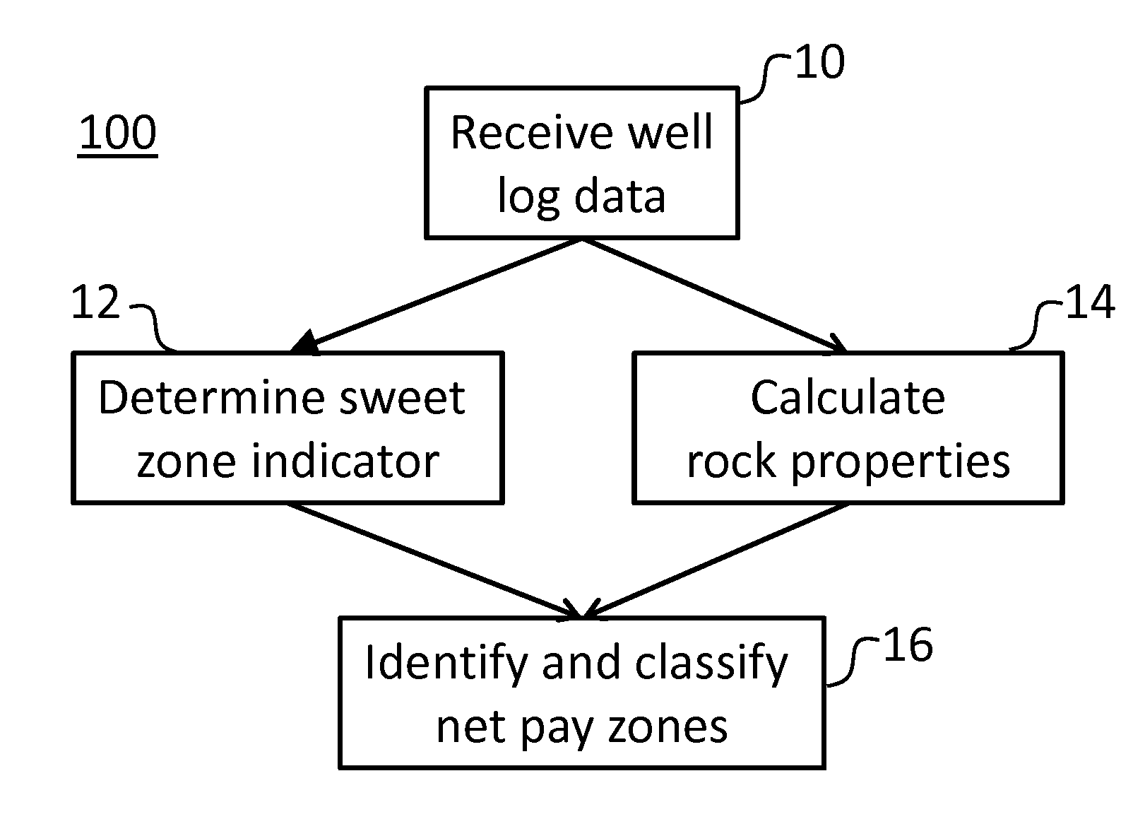
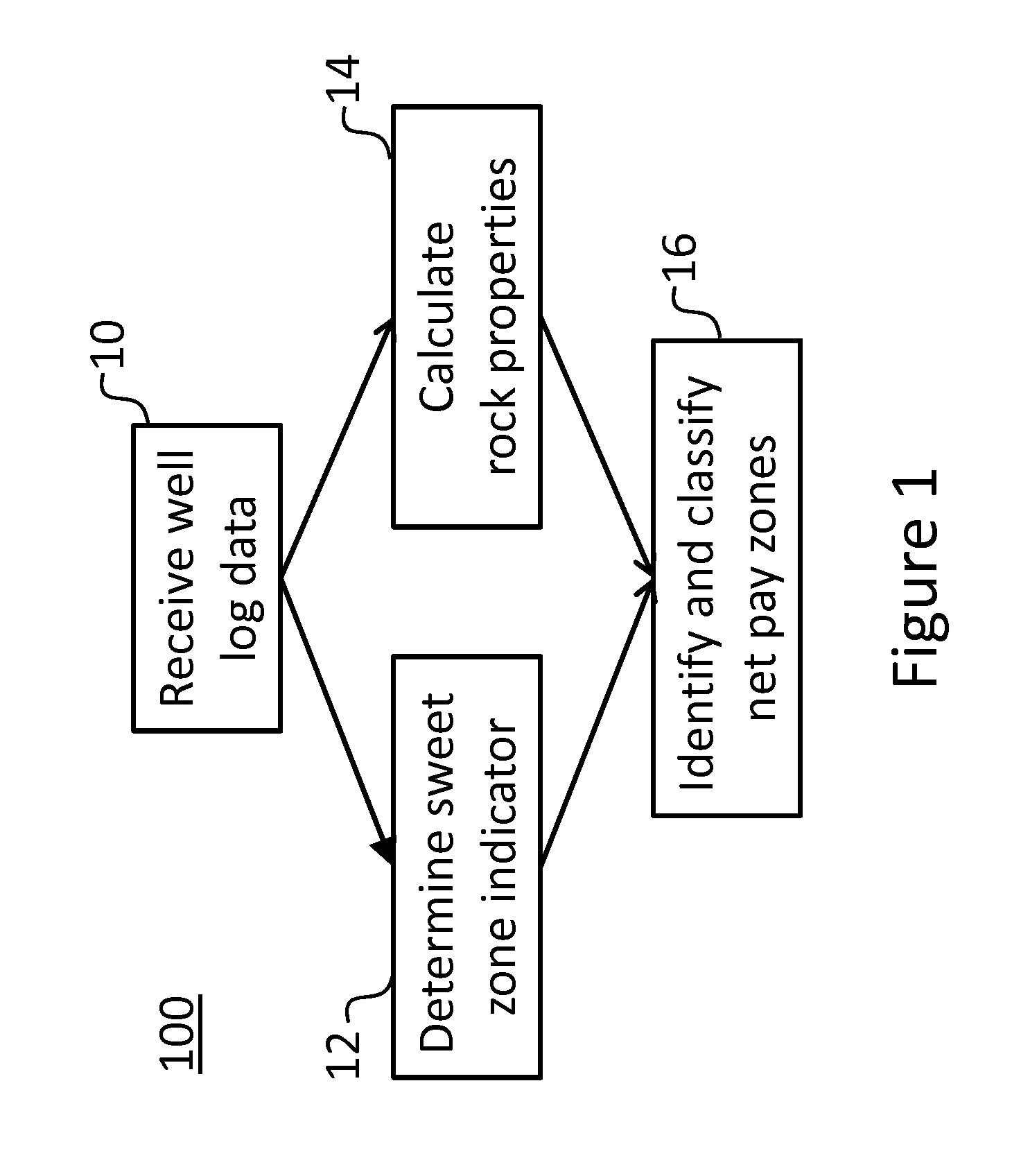
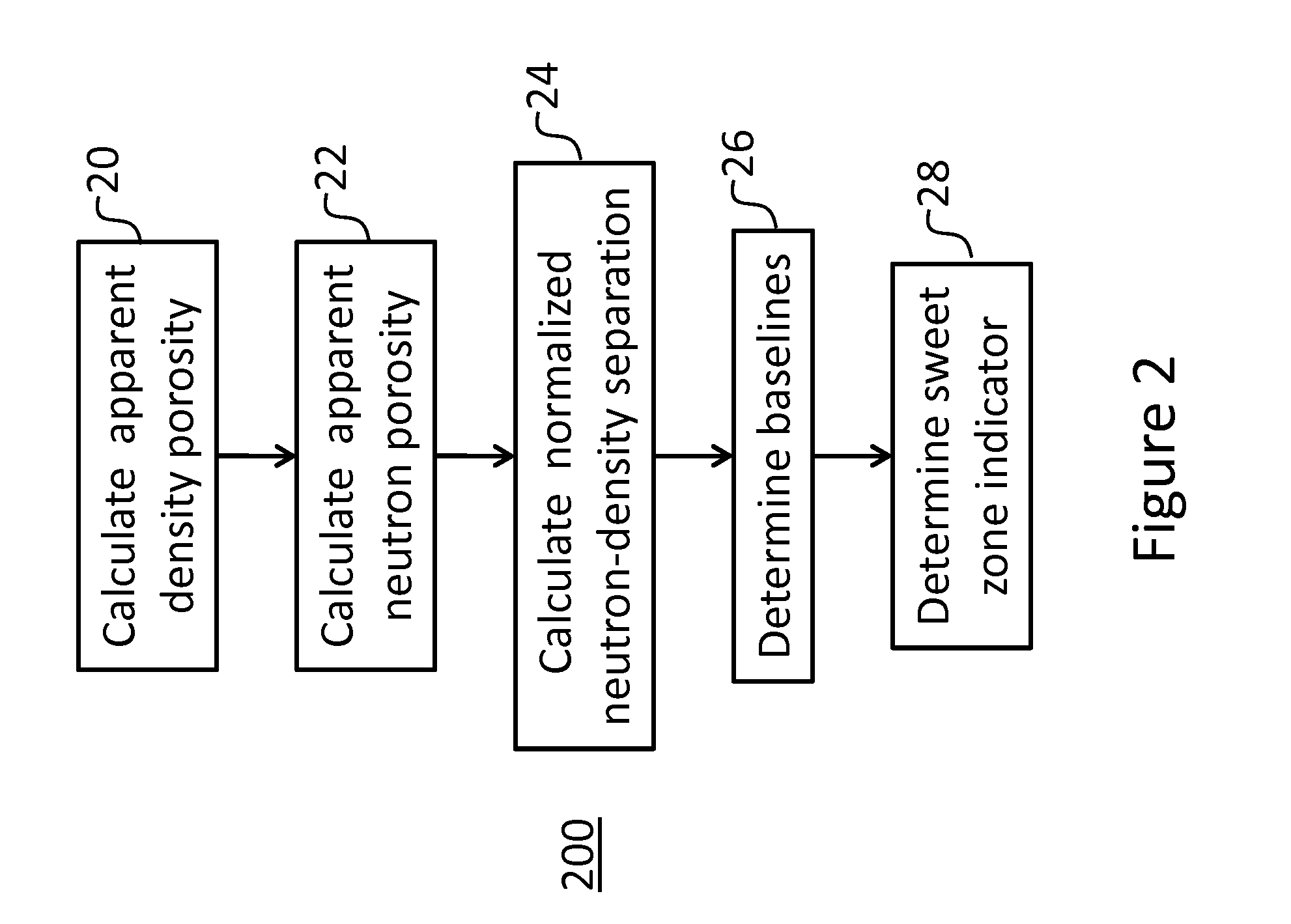
[0005]According to one implementation of the present invention, a computer-implemented method of characterizing hydrocarbon gas pay zones in a subterranean reservoir includes determining a sweet zone indicator based on well log data related to the reservoir, determining rock properties based on the well log data, deriving one or more classes of net pay zones from the sweet zone indicator and the rock properties, and outputting the net pay zones to identify areas of interest within the subterranean reservoir. The sweet zone indicator can be determined by calculating a normalized neutron-density separation and using the computed normalized neutron-density separation and well log data. The rock properties determined from the well log data may include total water saturation, adsorbed gas saturation, total gas content, porosity, propensity for hydraulic fracturing, uncertainty level of the total water saturation, uncertainty level of the total gas content, and baselines for the porosity and total gas content. The one or more classes of net pay zones may include first-class, second-class and third-class net pay zones that are characterized based on the sweet zone indicator and the rock properties.
[0006]In an embodiment, a system fo...

Problems solved by technology

In many cases, the existing methods are applicable only to the specific formation in which they have been applied, and do not have general relevance to new areas of exploration and development.

Method used


Image

  • System and method for hydrocarbon gas pay zone characterization in a subterranean reservoir
  • System and method for hydrocarbon gas pay zone characterization in a subterranean reservoir
  • System and method for hydrocarbon gas pay zone characterization in a subterranean reservoir

Examples


Embodiment Construction

[0012]The present invention may be described and implemented in the general context of a system and computer methods to be executed by a computer. Such computer-executable instructions may include programs, routines, objects, components, data structures, and computer software technologies that can be used to perform particular tasks and process abstract data types. Software implementations of the present invention may be coded in different languages for application in a variety of computing platforms and environments. It will be appreciated that the scope and underlying principles of the present invention are not limited to any particular computer software technology.

[0013]Moreover, those skilled in the art will appreciate that the present invention may be practiced using any one or combination of hardware and software configurations, including but not limited to a system having single and / or multiple computer processors, hand-held devices, programmable consumer electronics, mini-co...


PUM


Abstract

A system and computer-implemented method for characterizing hydrocarbon gas net pay zones in a subterranean reservoir including determining a sweet zone indicator from well log data, determining rock properties from well log data, and identifying one or more classes of net pay zones from the sweet zone indicator and rock properties. The sweet zone indicator may be determined by computing neutron-density separation and using the neutron-density separation and the well log data. The rock properties determined from the well log data may include total water saturation, adsorbed gas saturation, total gas content, porosity, propensity for hydraulic fracturing, uncertainty level of the total water saturation, uncertainty level of the total gas content, and baselines for the porosity and total gas content. Using the sweet zone indicator and rock properties, one or more classes of net pay zones can be identified.

Description

CROSS-REFERENCE TO RELATED APPLICATIONS[0001]This application is related to U.S. patent application Ser. No. 12 / 880,436 (Attorney Docket No. T-8135) entitled System and Method for Sweet Zone Identification in Shale Gas Reservoirs, which is incorporated in its entirety herein by reference.FIELD OF THE INVENTION[0002]The present invention relates generally to methods and systems for characterizing hydrocarbon gas pay zones in a subterranean reservoir, and in particular methods and systems for identifying and classifying net pay zones in shale gas reservoirs.BACKGROUND OF THE INVENTION[0003]“Net pay zones” can be used to characterize porous, permeable hydrocarbon gas reservoirs of commercial interest. Quick and accurate identification of net pay zones in wells, classification of the net pay zones, mapping of the net pay zones, and placement of horizontal wellbores within the best net pay zones are some of the most important tasks in gas exploration and development. This is especially t...

Claims


Application Information

Patent Timeline
IPC IPC(8): G06F19/00
CPCE21B49/00G01V11/00G01V20/00
Inventor LIU, CHENGBING
Owner CHEVROU USA INC
Learn More