Integrated cold junction compensation circuit for thermocouple connections

Inactive Publication Date: 2012-03-15
GENERAL ELECTRIC CO
View PDF5 Cites 25 Cited by
  • Summary
  • Abstract
  • Description
  • Claims
  • Application Information

AI Technical Summary

Problems solved by technology

However, having a junction of known temperature, while useful for laboratory calibration, is inconvenient for most measurement and control applications, particularly in lightweight, hand-held devices and permanent

Method used


Image

  • Integrated cold junction compensation circuit for thermocouple connections
  • Integrated cold junction compensation circuit for thermocouple connections
  • Integrated cold junction compensation circuit for thermocouple connections

Examples


Embodiment Construction

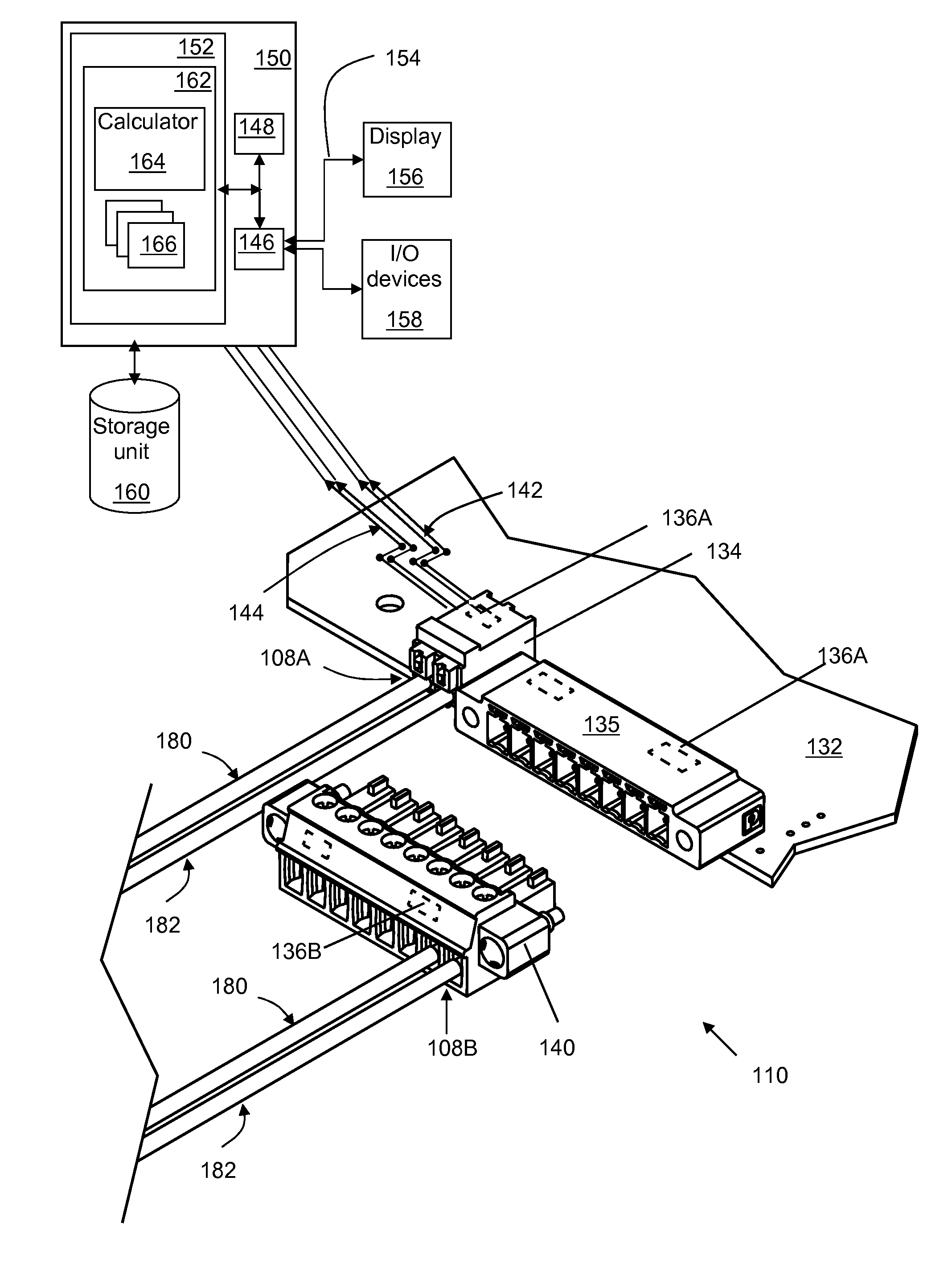
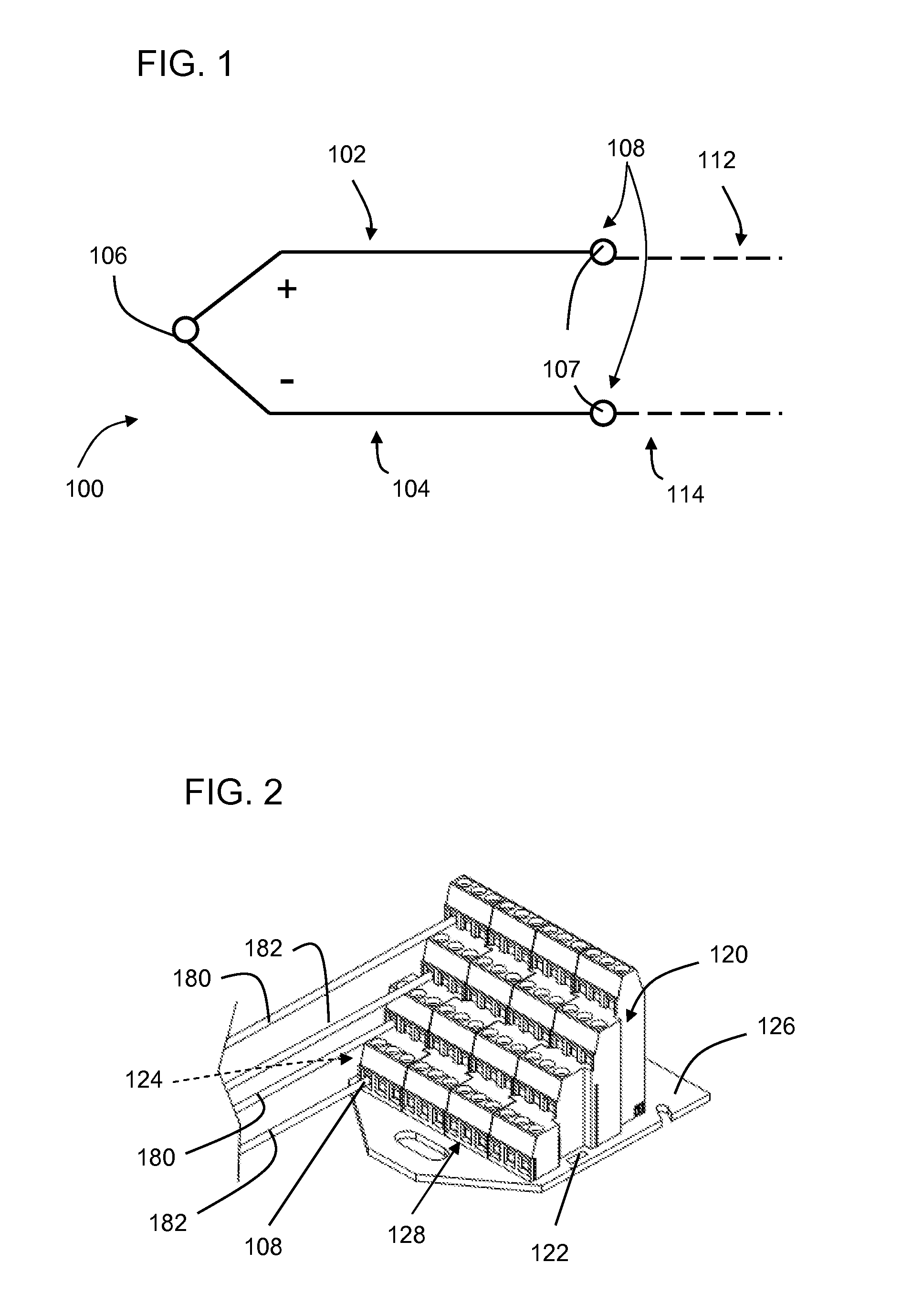
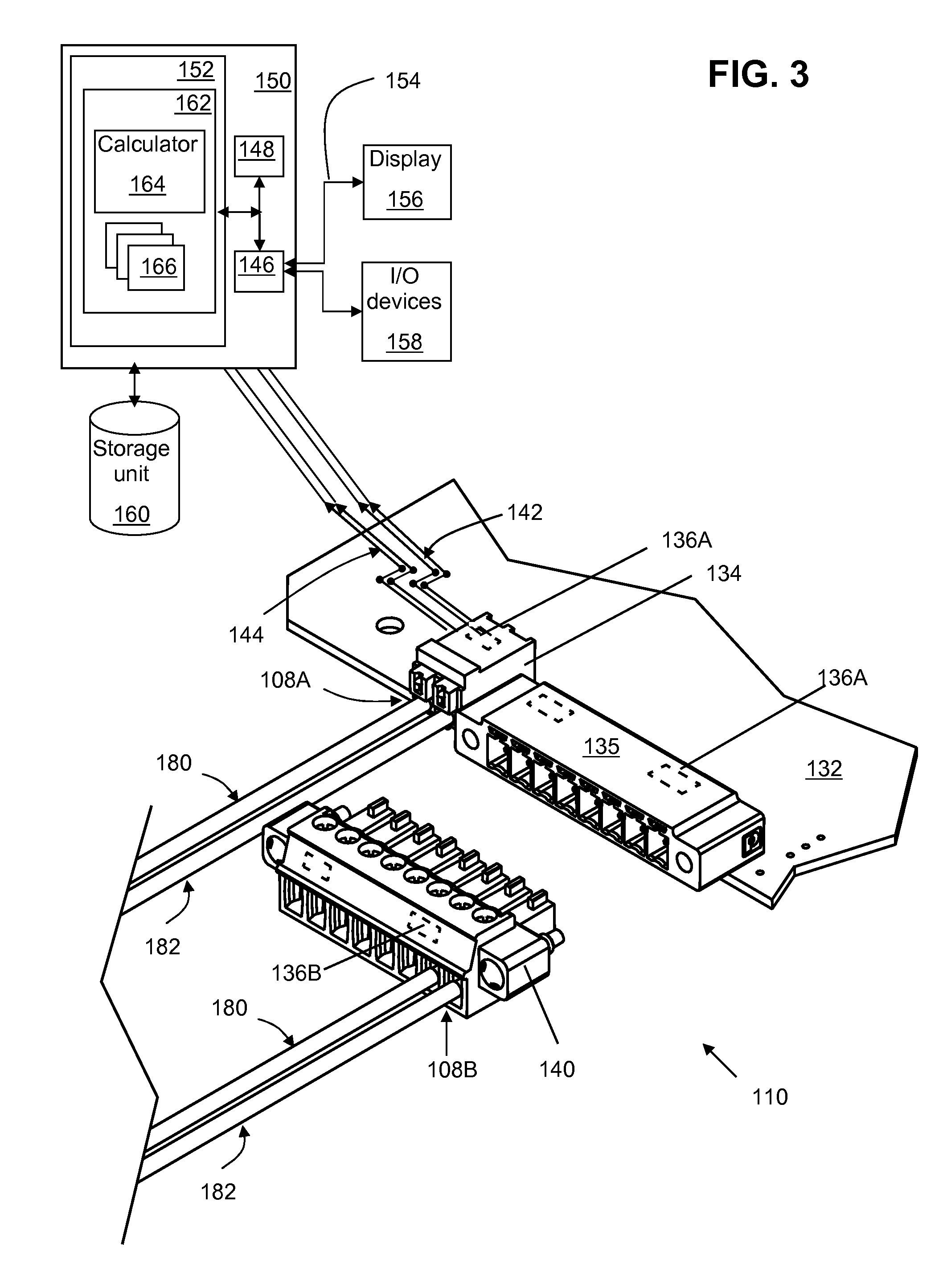
[0017]At least one embodiment of the present invention is described below in reference to its application in connection with the operation of a thermocouple cold junction compensation circuit. Although some of the embodiments of the invention are described herein and illustrated relative to a thermocouple in electrical communication with a printed circuit board, it is understood that the teachings are equally applicable to other substrates. Further, at least one embodiment of the present invention is described below in reference to a nominal size and including a set of nominal dimensions. However, it should be apparent to those skilled in the art that the present invention is likewise applicable to any suitable thermocouple cold junction measurement apparatus and / or device. Further, it should be apparent to those skilled in the art that the present invention is likewise applicable to various scales of the nominal size and / or nominal dimensions.

[0018]As indicated above, aspects of th...


PUM


Abstract

An integrated cold junction compensation system for a thermocouple connection is disclosed. The system includes a temperature sensor integrated with a terminal at which the thermocouple wires terminate. The temperature sensor is integrated with the terminal proximal to a cold junction of a thermocouple, such that the temperature at the sensor location is substantially equal to that at the cold junction. The temperature sensor is further in electrical signal isolation from a circuit carrying voltage output by the thermocouple.

Description

BACKGROUND OF THE INVENTION[0001]The disclosure relates generally to temperature measurement devices. More particularly, the invention relates to a cold junction compensation (CJC) circuit for thermocouple connections.[0002]A thermocouple is a junction between two dissimilar metals that produces an electric potential related to a temperature difference. As shown in the thermocouple of FIG. 1, thermocouple 100 is composed of two different thermocouple wires 102, 104 made of dissimilar metals. Wire 102 is designated positive, and wire 104 is designated negative. The positive and negative designations refer to the Seebeck coefficients of the respective metals of which the wires are made. Thermocouple wires 102, 104 are joined at tip 106, e.g., by soldering, welding, or other means. At screw terminals 107, the open ends of wires 102, 104 may electrically connect to wires or traces 112, 114, which may be made of copper or other electrically conductive material. A cold junction 108, or re...

Claims


Application Information

Patent Timeline
IPC IPC(8): G01K7/13G06F15/00G01K7/02
CPCG01K7/13G01K7/023
Inventor WHITELEY, JOSEPH LEE
Owner GENERAL ELECTRIC CO
Why Eureka
Try Eureka