Method and system for measuring entire thermal resistance of LED (light emitting diode) radiating module

A technology of heat dissipation module and measurement method, which is applied in the direction of measuring electrical variables, measuring electricity, measuring devices, etc., can solve the problems of few test conditions and results, inconvenient analysis of trends, and large differences in working characteristics, and achieves experimental data. Effective and reliable, simple structure, low cost effect

Inactive Publication Date: 2014-03-12
天津市易伸技术有限公司
View PDF9 Cites 14 Cited by
  • Summary
  • Abstract
  • Description
  • Claims
  • Application Information

AI Technical Summary

Problems solved by technology

[0007] However, the implementation of the above method has the following disadvantages: (1) the original circuit board wiring has been damaged beyond repair; (2) the dummy load is usually a resistive element, and its working characteristics are very different from those of LEDs, which cannot compensate the original circuit board. There are changes in the circuit; (3) LED represents only one sample. Since the steady-state temperature field is not uniformly distributed, different positions of the LED representative sample will often show different chip junction temperatures, which can only represent the The junction temperature of the position; (4) The heating power Q of a single LED single should be equal to the input electric power P E and luminous

Method used


Image

  • Method and system for measuring entire thermal resistance of LED (light emitting diode) radiating module
  • Method and system for measuring entire thermal resistance of LED (light emitting diode) radiating module
  • Method and system for measuring entire thermal resistance of LED (light emitting diode) radiating module

Examples


Embodiment

[0044] (1) Measurement of voltage temperature coefficient of LED lamp beads

[0045] Randomly extract 4 LED lamp beads that are the same as the production batch in the LED cooling module to be tested, and place them on the temperature control platform of the SSP8810-S LED Light Color Thermoelectric Performance Comprehensive Tester (hereinafter referred to as the SSP8810-S Tester). On, with a test current of 10mA, the temperature control platform was obtained at a low temperature T l and high temperature T h The forward test voltage of the LED when V l and V h , and then calculate the voltage temperature coefficient K of the LED device by formula (1). The specific data are shown in Table 1.

[0046] K = V h - V 1 T h - T ...


PUM


Abstract

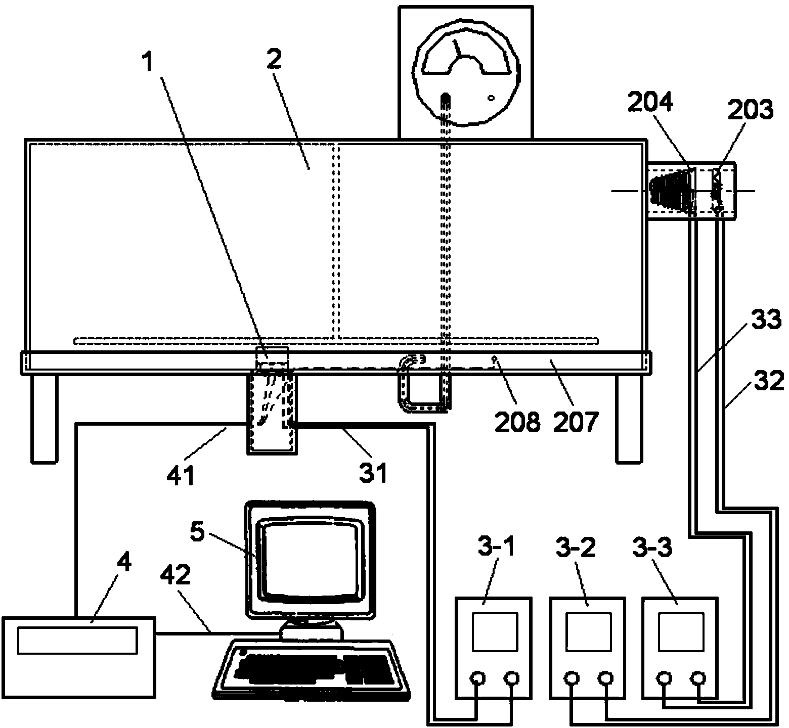
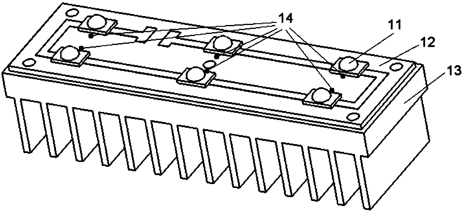
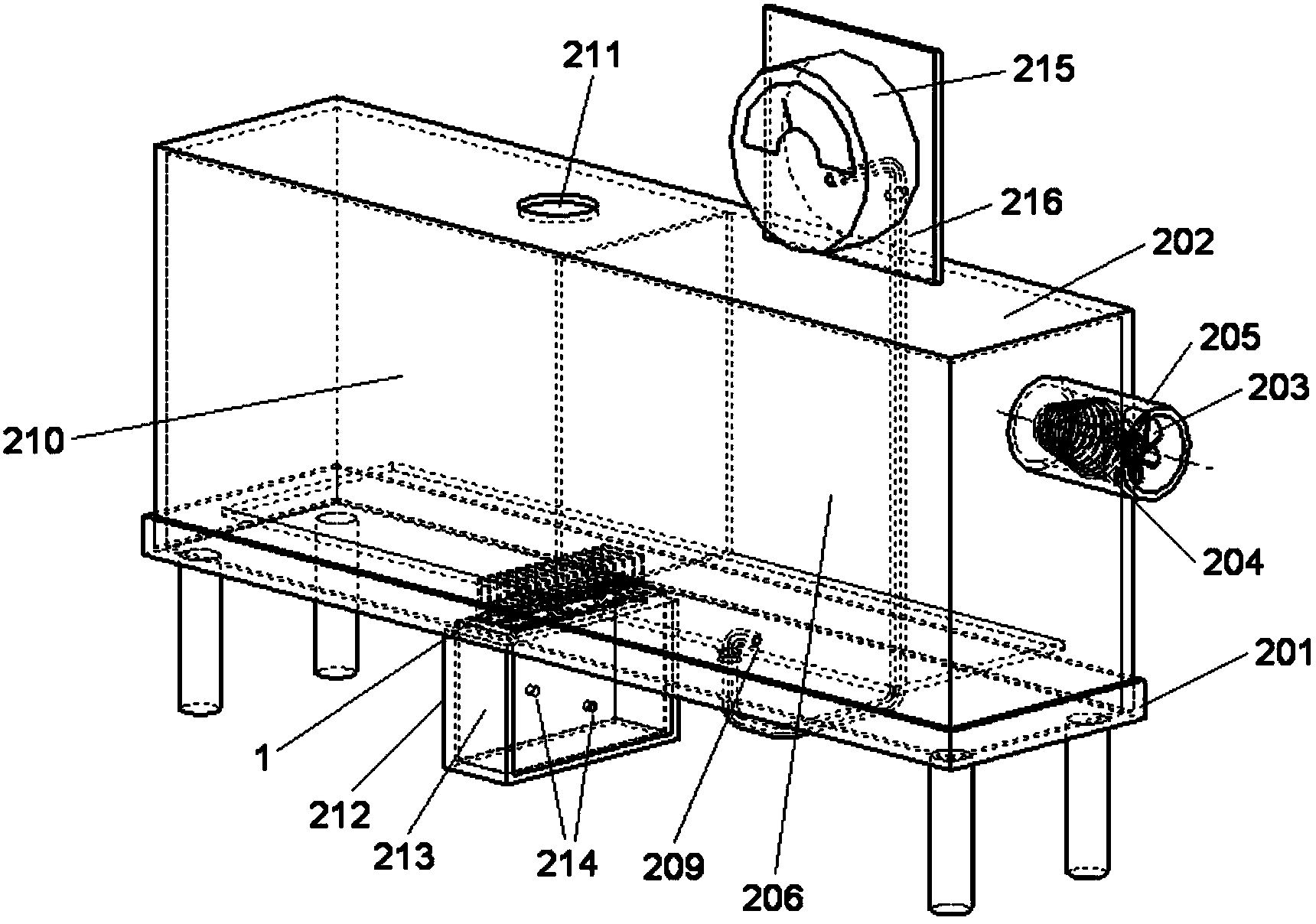
The invention discloses a method and a system for measuring the entire thermal resistance of an LED (light emitting diode) radiating module. The method is simple; and the method and the system are high in practicality. The system comprises an LED radiating module, an environmental simulation testing box, a temperature recorder and a power control system, wherein an inlet air pressure voltage-stabilizing chamber, a testing air duct and an outlet air pressure voltage-stabilizing chamber are formed in the environmental simulation testing box; the testing air dust is connected with the inlet air pressure voltage-stabilizing chamber and the outlet air pressure voltage-stabilizing chamber; an air inlet is formed in a box body and corresponds to the inlet air pressure voltage-stabilizing chamber; an air flow driving device and an air heating device are arranged at an air inlet; an air outlet is formed in the box body and corresponds to the outlet air pressure voltage-stabilizing chamber; an air temperature testing point is arranged in the testing air duct; the LED radiating module is arranged in the testing air duct; temperature measuring probes are arranged at a temperature measuring reference point and an air temperature testing point of the LED radiating module; and a temperature signal output end of each temperature measuring probe is connected with a thermocouple wire of the temperature recorder. The system is easy to operate; and obtained data are effective and reliable.

Description

technical field [0001] The invention relates to the technical field of LED performance testing, in particular to a method and a measurement system for measuring the total thermal resistance of an LED cooling module. Background technique [0002] High-power LEDs have a series of significant performance advantages such as low power consumption, long life, small size, and rapid response. With their wide application in many lighting fields, LED lamps have become a promising alternative to incandescent lamps, fluorescent lamps and halogen lamps. Lamps and other traditional light sources of new lighting products. Because the heat dissipation ability of LED can directly affect its performance index, service life and working reliability, the analysis of LED heat dissipation performance is very important. [0003] In the analysis of LED heat dissipation performance, the size of the total thermal resistance value can objectively measure the heat dissipation capacity of different lamp...

Claims


Application Information

Patent Timeline
IPC IPC(8): G01R31/44G01R31/27
Inventor 张建新王巍牛萍娟王景祥刘涛代静李松宇付豪张东
Owner 天津市易伸技术有限公司
Why Eureka
Try Eureka