Supercharge Your Innovation With Domain-Expert AI Agents!

Ultrasonic Testing System

a testing system and ultrasonic technology, applied in the direction of material magnetic measurements, and solid analysis using sonic/ultrasonic/infrasonic waves, can solve the problems of insufficient sensitiveness, inability to use piezoelectric ultrasonic probes, and inability to use laser ultrasonics or electro-magnetic-acoustic transducers (emat test methods),

Inactive Publication Date: 2012-03-22
FLOHR GUIDO +1
View PDF1 Cites 8 Cited by
  • Summary
  • Abstract
  • Description
  • Claims
  • Application Information

AI Technical Summary

Benefits of technology

"The invention relates to an ultrasonic testing system for metallic materials that uses a laser to generate and detect vibrations on the surface of the material. This system can provide a non-destructive and cost-effective way to test for quality management purposes. The laser-optical system can be used for specific problems in ultrasonic testing, such as the difficulty of testing cold materials and the presence of surface defects that can cause error indications during ultrasonic testing. The use of a laser to excite the material surface and measure the vibrations can provide more accurate and reliable results, and can also allow for faster and safer testing. The invention also includes a method for using the laser-optical system for testing the thickness of metallic plates and the surface quality of heavy plates during production."

Problems solved by technology

In the case of hot or fast-moving products, conventional testing using piezoelectric ultrasonic probes is not possible.
Alternative methods such as laser ultrasonics or electro-magnetic-acoustic transducers (EMAT test method) are either very expensive or, in the case of free ultrasonic waves, are not sensitive enough.
The expense in terms of apparatus or electronics is very high in this case.
As a result of, for example spots of grease or oil on the surface or due to other impurities or to uneven surfaces, the probe-to-specimen contact can break off or change, which leads more frequently to pseudo error indications.

Method used


Image

  • Ultrasonic Testing System
  • Ultrasonic Testing System
  • Ultrasonic Testing System

Examples


Embodiment Construction

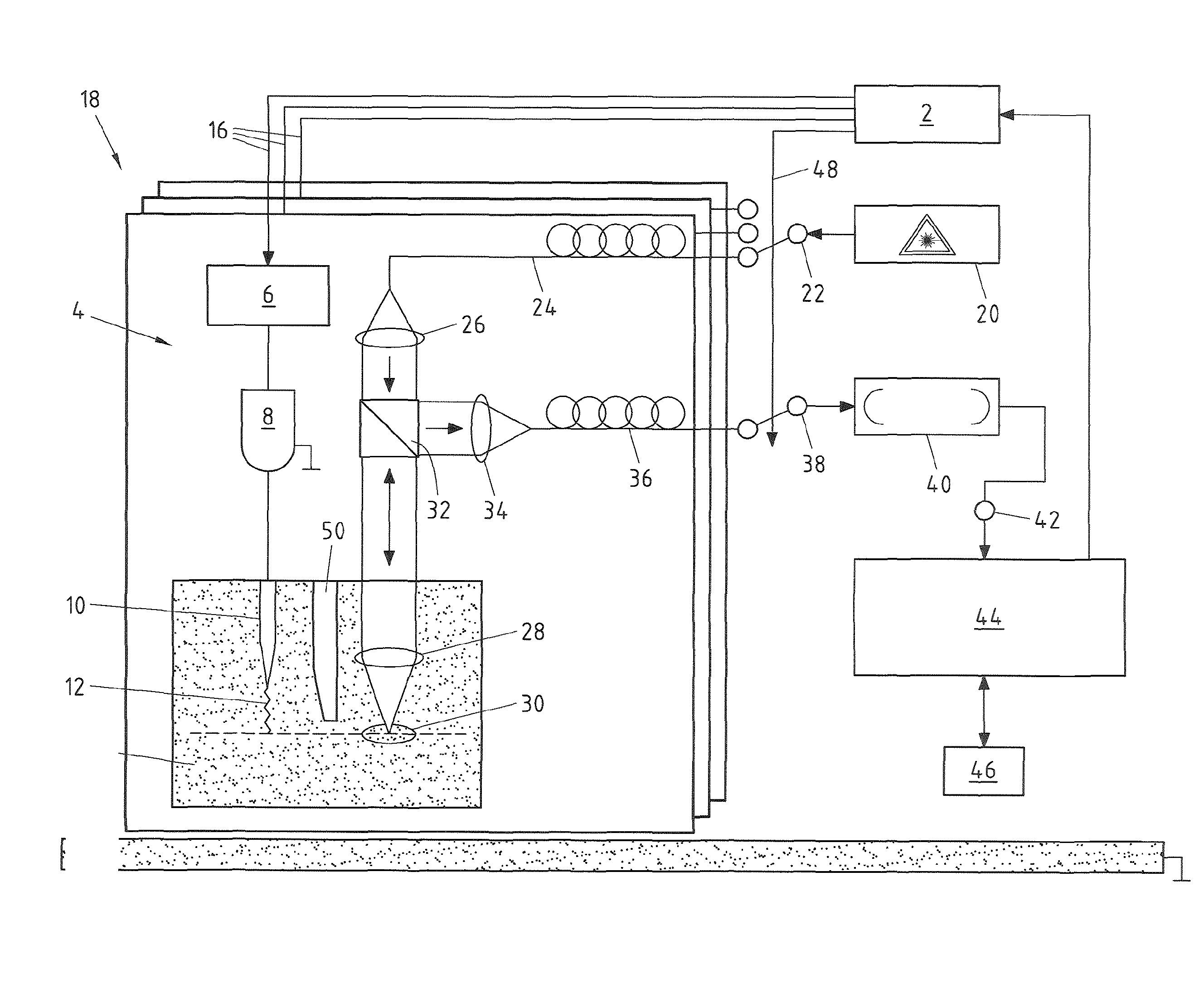
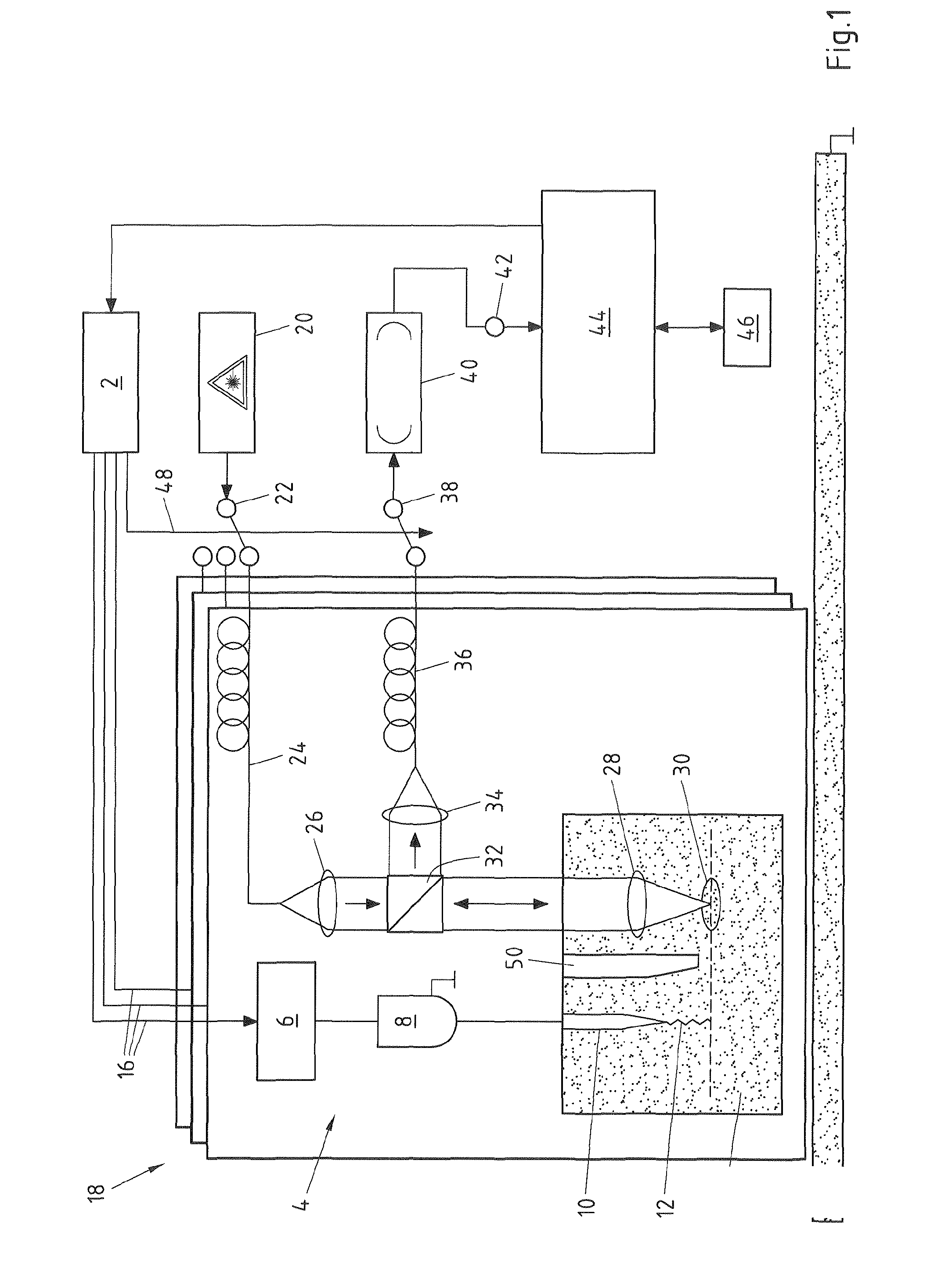
[0089]FIG. 1 shows an ultrasonic testing system according to an embodiment of the invention which is provided with a transmitting apparatus, according to an embodiment of the invention, and a receiving system, according to an embodiment of the invention. Furthermore, a method, according to an embodiment of the invention, can be carried out using this ultrasonic testing system.

[0090]The measuring arrangement illustrated in FIG. 1 firstly comprises a control 2 which performs and coordinates the control of the components, described in the following, of the ultrasonic testing system.

[0091]First of all, the mode of operation of a transmitting apparatus 4 for an ultrasonic testing system for testing a test object will be explained. The transmitting apparatus 4 comprises transmitting electronics 6, an ignition coil 8 and an electrode 10 which together form a transmitting apparatus. The ignition coil 8, together with the electrode 10, presents means for generating a spark gap 12, wherein th...


PUM

PropertyMeasurementUnit
poweraaaaaaaaaa
transport speedaaaaaaaaaa
widthaaaaaaaaaa

Abstract

An ultrasonic testing system for testing a test object that includes at least one transmitting unit and at least one receiver unit. In an embodiment, the transmitting unit generates a spark gap which generates an ultrasonic vibration either on the surface of, or within, the test object. In particular embodiment, the at least one receiver unit optically measures the vibration of the surface of the test object. Embodiments of the invention also relate to a transmitting means and to a receiving system for an ultrasonic testing system and to a method for operating an ultrasonic testing system.

Description

CROSS-REFERENCE TO RELATED PATENT APPLICATIONS[0001]This patent application is a continuation of PCT / EP2010 / 054954, filed Apr. 15, 2010, which claims priority to German Application No. 102009017106.1, filed Apr. 15, 2009, the entire teachings and disclosure of which are incorporated herein by reference thereto.FIELD OF THE INVENTION[0002]The invention generally relates to ultrasonic testing systems.BACKGROUND OF THE INVENTION[0003]Embodiments of the invention represent an improvement over the state of the art with respect to ultrasonic testing systems. These and other advantages of the invention, as well as additional inventive features, will be apparent from the description of the invention provided herein.BRIEF SUMMARY OF THE INVENTION[0004]Embodiments of the invention relate to an ultrasonic testing system comprising at least one transmitting unit and at least one receiver unit, to a transmitting apparatus for an ultrasonic testing system for testing a test object, comprising at ...

Claims


Application Information

Patent Timeline
Patent Type & Authority Applications(United States)
IPC IPC(8): G01N29/04
CPCG01N21/1702G01N21/67G01N2291/2626G01N29/2431G01N2021/1706G01N29/2418G01N29/04G01B9/02
Inventor OBERHOFF, DIETMARFLOHR, GUIDO
Owner FLOHR GUIDO
Features
  • R&D
  • Intellectual Property
  • Life Sciences
  • Materials
  • Tech Scout
  • Unparalleled Data Quality
  • Higher Quality Content
  • 60% Fewer Hallucinations
Learn More