Apparatus for and method of controlling variable valve timing mechanism

a timing mechanism and valve technology, applied in the direction of electric control, engine starters, machines/engines, etc., can solve the problems of increasing the power consumption at the time of internal combustion engine startup, increasing the cranking time, and slowing down the engine speed in the cranking state, so as to reduce the vibratory force and reduce the power consumption

Inactive Publication Date: 2012-03-22
HITACHI ASTEMO LTD
View PDF15 Cites 21 Cited by
  • Summary
  • Abstract
  • Description
  • Claims
  • Application Information

AI Technical Summary

Benefits of technology

[0008]It is therefore an object of the present invention to provide an apparatus for and a method of controlling a variable valve timing mechanism that can decrease power consumption, while suppressing pre-ignition and decreasing vibratory force at the time of startup of the internal combustion engine.

Problems solved by technology

However, if the effective compression ratio is low, the combustion torque of the internal combustion engine decreases, and hence, the rise in engine speed in the cranking state becomes slow, and cranking time increases.
Consequently, in the control by the controller in which completion timing of the control for causing the closing timing of the intake valve to approach piston bottom dead center is retarded, power consumption at the time of startup of the internal combustion engine is increased.

Method used


Image

  • Apparatus for and method of controlling variable valve timing mechanism
  • Apparatus for and method of controlling variable valve timing mechanism
  • Apparatus for and method of controlling variable valve timing mechanism

Examples


Embodiment Construction

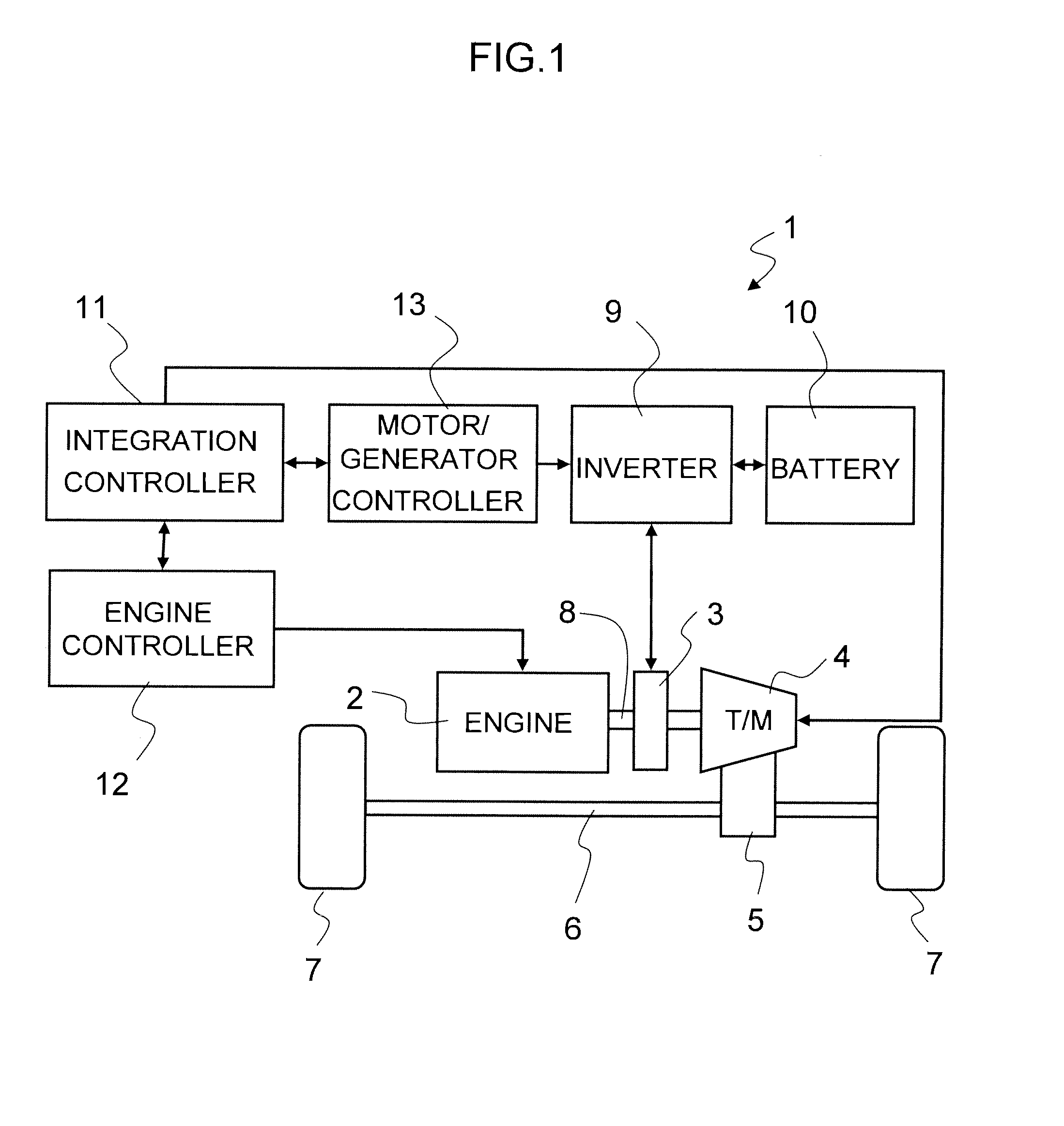
[0022]A hybrid vehicle 1 shown in FIG. 1 includes two power sources, that is, an internal combustion engine 2, which employs the apparatus for and method of controlling a variable valve timing mechanism according to the present invention, and an electric motor 3, which is an AC motor.

[0023]A driving force of internal combustion engine 2 is transmitted to drive wheels 7 via a transmission 4, a differential gear 5, and an axle 6.

[0024]A rotor of electric motor 3 is directly connected to an output shaft 8 between internal combustion engine 2 and transmission 4. Alternatively, output shaft 8 and the rotor of electric motor 3 may be connected via a power transmission mechanism such as a gear.

[0025]Electric motor 3 is a motor / generator. When being operated as an electric motor, electric motor 3 outputs a driving force for vehicle 1. Moreover, electric motor 3 is rotated by internal combustion engine 2 or drive wheels 7, thereby operating as an electric generator and outputting power.

[0026...


PUM


Abstract

The present invention relates to an apparatus for and a method of controlling a variable valve timing mechanism. The valve timing mechanism changes over between a first cam for which the closing timing IVC of the intake valve is after intake bottom dead center, and a second cam for which the closing timing IVC is closer to intake bottom dead center than the closing timing IVC with the first cam. Here at the time of stopping the internal combustion engine, the valve timing mechanism changes over to the first cam, and the initial intake stroke performs operation at low effective compression ratio. In the second and subsequent intake strokes, the valve timing mechanism changes from the first cam to the second cam.

Description

BACKGROUND OF THE INVENTION[0001]1. Field of the Invention[0002]The present invention relates to an apparatus for and a method of controlling a variable valve timing mechanism that changes the closing timing of an intake valve of an internal combustion engine.[0003]2. Description of Related Art[0004]Japanese Laid-open Patent Publication No. 2010-138737 discloses a controller of a variable operating angle mechanism capable of changing an operating angle of an intake valve. The controller controls the operating angle of the intake valve before startup of the internal combustion engine, so that the closing timing of the intake valve becomes after piston bottom dead center. Then in a startup state from input of a command signal for starting up the internal combustion engine until combustion starts, if the temperature of the internal combustion engine is lower than a threshold, the operating angle of the intake valve is made smaller that before startup, so that the closing timing of the ...

Claims


Application Information

Patent Timeline
Patent Type & Authority Applications(United States)
IPC IPC(8): F01L1/34
CPCF02D13/0226F01L2800/01F02D13/0265F02D41/042F02D41/065F02D2200/023F02D2200/0414F02D2200/1015F02N11/0814Y02T10/18F01L1/18F01L1/34F01L13/0036F01L2001/186F01L2001/34453F02D13/0238Y02T10/12
Inventor MURAI, ATSUSHIMURAKAMI, TOMOYUKINAKAMURA, YOSHITATSU
Owner HITACHI ASTEMO LTD
Why Eureka
Try Eureka