Hydraulic system and a working machine comprising such a hydraulic system

a technology of hydraulic system and working machine, which is applied in the direction of couplings, valve details, gas/liquid distribution and storage, etc., can solve the problems of energy loss, energy loss (heat), energy loss,

Active Publication Date: 2012-03-22
VOLVO CONSTR EQUIP
View PDF10 Cites 36 Cited by
  • Summary
  • Abstract
  • Description
  • Claims
  • Application Information

AI Technical Summary

Benefits of technology

[0020]Furthermore, conditions are created for enabling the part of the hydraulic system related to energy recovery to be designed as a separate unit, which can be connected to a given hydraulic system. Such a separate unit can be connected to the return side of one or several work functions in different types of hydraulic systems. Accordingly, an energy recovery system can be built as a separate unit and be offered as an option to a standard system. In the following text, the expression “energy recovery system” will be used for the part of the hydraulic system capable of constituting such a separate unit which can be connected to a base system in a simple manner.
[0021]The hydraulic system preferably comprises a pump, hereinafter also called a main pump or supply pump, for providing hydraulic fluid to said at least one work function. Such a pump can be adapted to supply one or several work functions with hydraulic fluid. According to one embodiment of the invention, the hydraulic system comprises a means for returning energy, recovered from a return flow from the work function, to the pressure side of the pump. This offers a possibility to recover energy which is then used to assist the main pump in supplying one or several work functions. This in its turn creates conditions for solving, or at least reducing, the problem of providing enough energy to drive the hydraulic system and the driveline at low engine speeds in a working machine. The main pump in a hydraulic system of the kind in question is namely usually mechanically connected to the engine of the working machine, such as a diesel motor, which is used to drive both the hydraulic system and the driveline for propelling the working machine. The speed of the main pump will thus become dependent on the speed of the diesel engine. The speed of the diesel engine, in its turn, depends on the desired propulsion speed of the working machine and the torque determined by the actual operation mode.

Problems solved by technology

In the present hydraulic systems of load sensing type, energy which could be recovered is lost.
Here, a pressure drop usually occurs across the control valve, since the returned hydraulic oil is drained to tank, which in its turn results in an energy loss (heat).
This back up pressure, in its turn, leads to energy losses.
These work functions may, however, require different pressures, meaning that the pump has to be adjusted according to the highest required pressure.
The pressure drop which arises across the control valve for the work function requiring the lowest pressure results in an energy loss,
Even though the recovery unit is adapted to the actual hydraulic system, in some cases it could happen that all energy which potentially can be recovered at a certain point in time cannot be stored or consumed instantaneously.
Such an excessive pressure could be the result of the system having a pump operating at a constant pressure level, but it is more common when using one and the same pump for two or more work functions that different pressures are required for the work functions and the pump pressure then has to be adapted to the work function requiring the highest pressure.

Method used


Image

  • Hydraulic system and a working machine comprising such a hydraulic system
  • Hydraulic system and a working machine comprising such a hydraulic system
  • Hydraulic system and a working machine comprising such a hydraulic system

Examples


Embodiment Construction

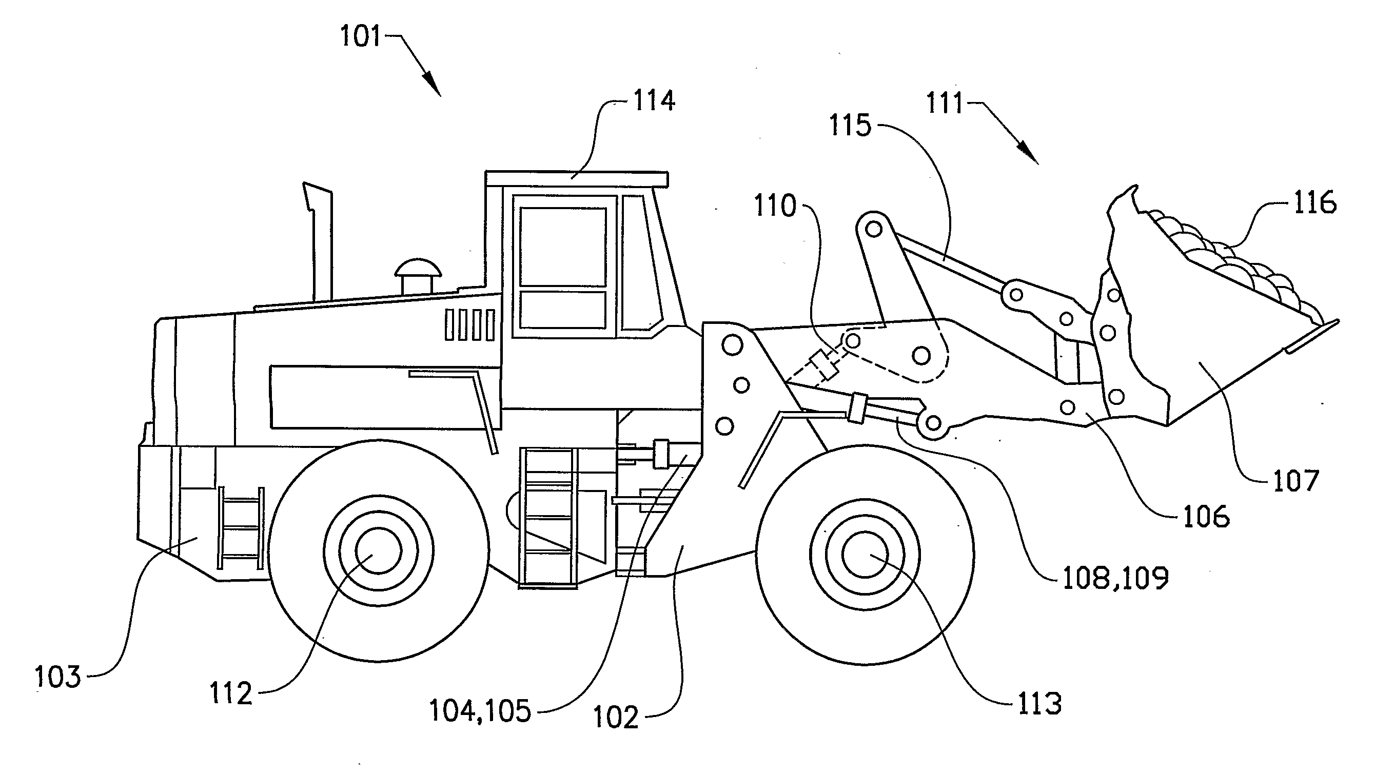
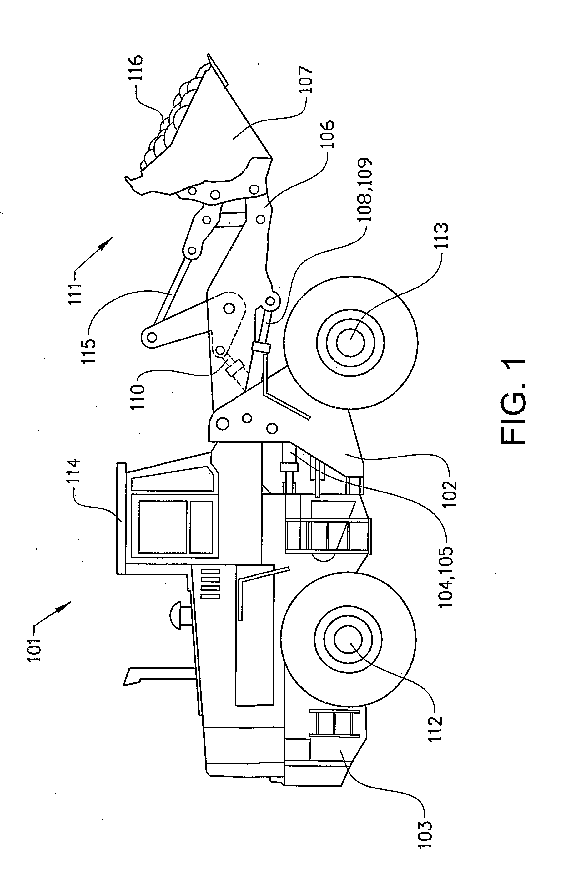
[0041]FIG. 1 shows a working machine in the form of a wheel loader 101. The wheel loader 101 should be seen as an example of a working machine to which the hydraulic system according to the invention can be applied. The wheel loader 101 comprises a front vehicle section 102 and a rear vehicle section 103. Each of these vehicle sections 102, 103 comprise a frame and wheels arranged on a drive axle 112, 113. The rear vehicle section 103 comprises an operator's cab 114. The vehicle sections 102, 103 are connected to each other in such a way that they can be pivoted relative to each other about a vertical axis by means of two hydraulic cylinders 104, 105, called steering cylinders, which are connected to the two vehicle sections 102, 103. Accordingly, the hydraulic cylinders 104, 105 are disposed on different sides of a centre line, extending in the longitudinal direction of the vehicle, for steering or turning the wheel loader 101 by means of the hydraulic cylinders. In other words, th...


PUM


Abstract

A hydraulic system for a working machine includes at least one work function and a control valve unit for controlling hydraulic fluid to and from the work function, and a recovery unit connected to a return port of the control valve unit for recovering energy from the work function. The system further includes an arrangement for limiting the pressure of the hydraulic fluid at the return port, which pressure limiting arrangement has a pilot-operated valve adapted to set a maximum allowable pressure at the return port of the control valve unit. The pressure is variable by controlling the pilot-operated valve by a control unit.

Description

BACKGROUND AND SUMMARY[0001]The present invention relates to a hydraulic system. The invention also relates to a working machine comprising the hydraulic system.[0002]A working machine in the form of a wheel loader has a plurality of different work functions which are controlled hydraulically, such as lifting and tilting of an implement and steering (frame steering) of the working machine. The control of the respective work function is performed via hydraulic actuators; such as linear motors in the form of hydraulic cylinders.[0003]Below, the invention will be described in connection with the operation of a wheel loader. This is a preferred, but by no means limiting application of the invention. The invention can also be utilized for other types of working machines or working vehicles having hydraulic work functions. It could for example also be an articulated hauler, a backhoe loader, an excavator, or an agricultural machine such as a tractor.[0004]The present hydraulic systems are...

Claims


Application Information

Patent Timeline
Patent Type & Authority Applications(United States)
IPC IPC(8): F15B1/02F15B13/00
CPCE02F9/2217F15B2211/88E02F9/2296F15B21/14F15B2211/20546F15B2211/3057F15B2211/3111F15B2211/6309F15B2211/6313F15B2211/6336F15B2211/634F15B2211/6346F15B2211/7121F15B2211/7128E02F9/2292Y10T137/0396Y10T137/7762F15B13/0433
Inventor VIGHOLM, BOEKVALL, ANDREASHEYBROEK, KIM
Owner VOLVO CONSTR EQUIP
Why Eureka
Try Eureka