Glass with terminal

Inactive Publication Date: 2012-03-22
3M INNOVATIVE PROPERTIES CO +1
View PDF22 Cites 14 Cited by
  • Summary
  • Abstract
  • Description
  • Claims
  • Application Information

AI Technical Summary

Benefits of technology

[0025]The terminal includes the bent portion bent toward the silver print. A spring structure is obtained by bending the terminal, which urges the terminal in the direction of contact relative to the silver print. According to this structure, contact strength can be increased, which otherwise may be inadequate when only adhesive is used, and thus sufficient contact strength can be obtained.
[0026]The base part is thinner than the terminal part. By forming the base part thinner than the terminal part, the separation of the terminal due to repulsive force of the base part can be prevented, and the size of the terminal can be reduced.
[0027]The terminal is bonded to the glass at the non-printed area where the silver print is not applied. In other words, an adhesive layer for bonding the terminal to the glass is directly disposed on the upper surface of the glass. When the adhesive layer is disposed directly on the upper surface of the glass, as compared to an adhesive layer disposed on the upper surface of the silver print, initial adhesion strength is equivalent to that of the latter, but a remarkable effect (78.4 N or more) is verified through a humidity resistance test (50° C., RH 90% or higher, for 720 hrs). The non-printed area also includes, besides the glass surface, a black ceramic print area printed on the glass s

Problems solved by technology

A space inside the interior finishing material is limited, and the terminal has to be arranged inside the limited space.
Fur

Method used


Image

  • Glass with terminal
  • Glass with terminal
  • Glass with terminal

Examples


embodiment 1

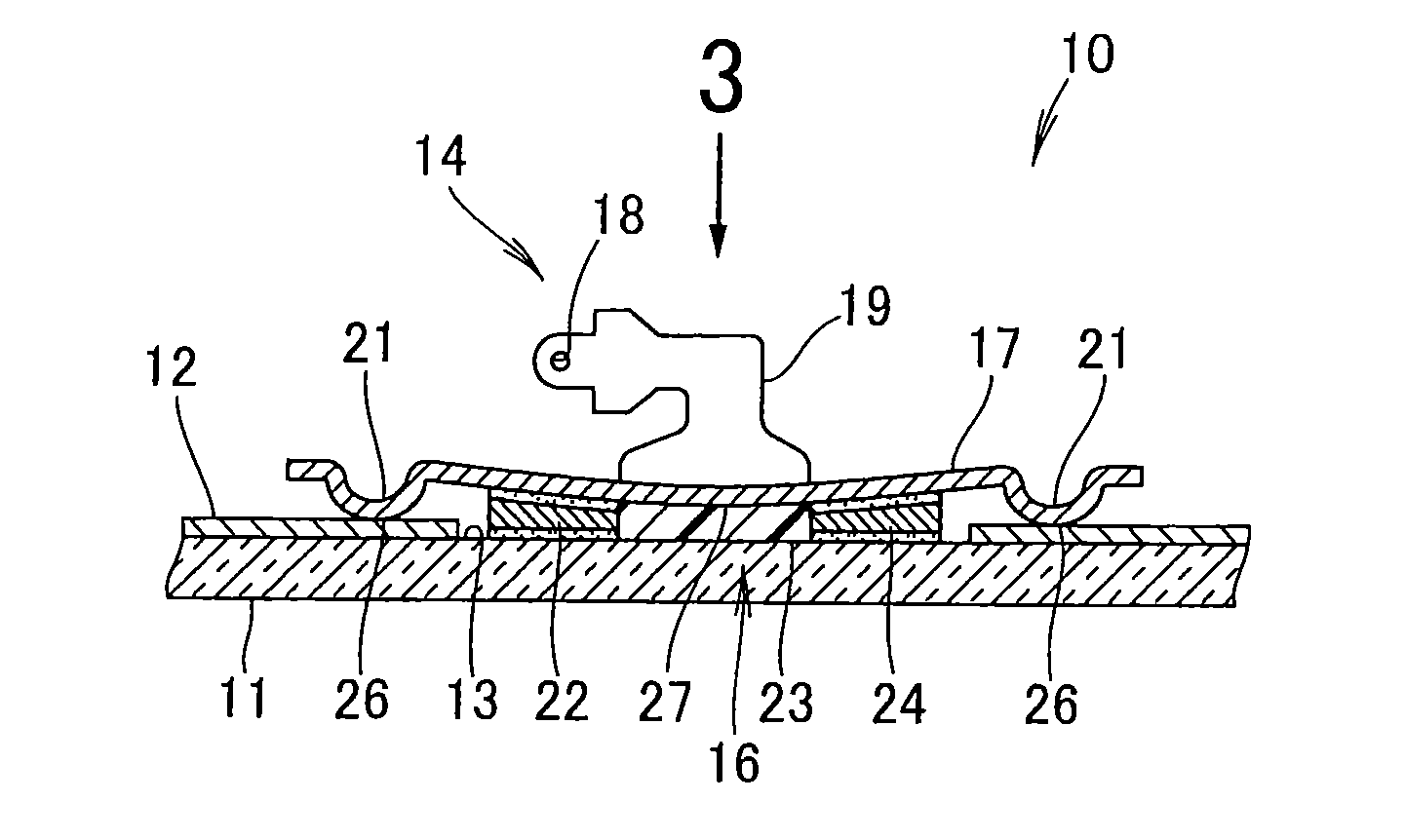
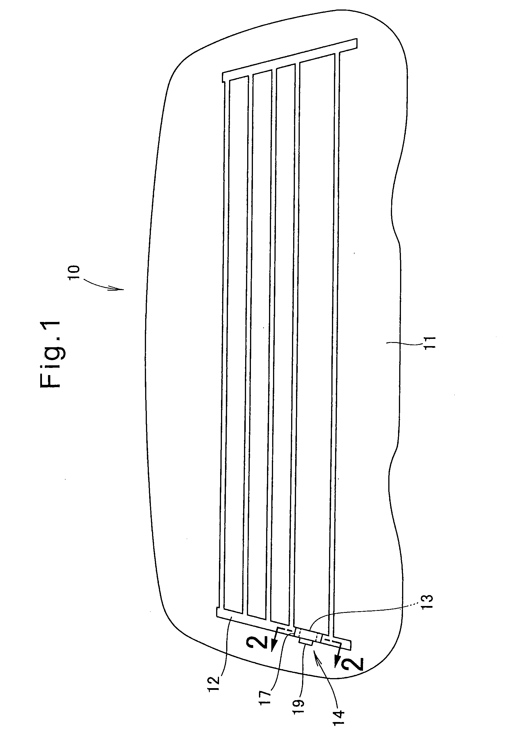
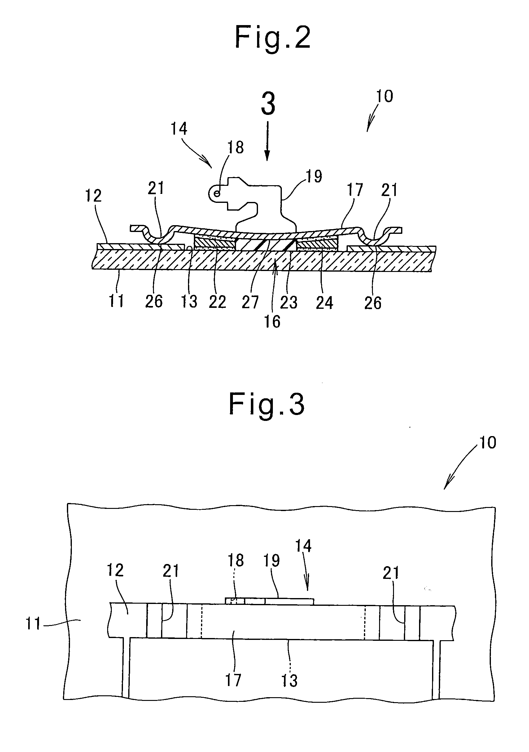
[0049]FIGS. 1 to 4 depict embodiment 1 of the present invention. Referring to FIG. 1, a glass-with-terminal 10 includes a glass 11 such as a window pane of a vehicle, a silver print 12 provided on the surface of the glass 11 and capable of functioning as an antenna, a non-printed area 13 free of the silver print 2, and a terminal 14 bonded to the glass 11 at the non-printed area 13 and electrically connecting vehicle-mounted units to the silver print 12.

[0050]Non-printed area 13 can be formed by masking a part of the surface of the glass 11 during a printing process of the silver print 12. Alternatively, it may be formed by cutting away a part of the silver print 12 after the silver print has been provided. Thus, a process of forming the non-printed area 13 can be optionally selected, as long as a resultant non-printed portion is obtained. It is advantageous to adopt the process of masking a part of the surface of the glass 11, since the non-printed area 13 can be formed in a short ...

embodiment 2

[0073]In the case where a non-printed area 29 is formed in the shape of a U-groove as depicted in FIG. 5(a), the terminal 14 also can be electrically connected to the silver print 12 as depicted in FIG. 5(b). Even in this case, the adhesive layer is directly disposed on the upper surface of the glass, which can bring about an advantageous effect of the present invention such that the adhesive layer is bonded to the glass with higher adhesion strength.

embodiment 3

[0074]In the case where a non-printed area 31 is formed in the shape of a window as depicted in FIG. 6(a), the terminal 14 also can be electrically connected to the silver print 12 as depicted in FIG. 6(b). Even in this case, the adhesive layer is directly disposed on the upper surface of the glass, which can bring about an advantageous effect of the present invention such that the adhesive layer is bonded to the glass with higher strength.


PUM


Abstract

A glass-with-terminal, in which a terminal is bonded to a glass without using solder, is disclosed. The glass-with-terminal has a configuration wherein a terminal (14) is bonded to a glass (11) provided on the surface thereof with a silver print (12). The terminal (14) includes a bent portion (21) formed, in at least one end of the terminal, to be bent toward the silver print (12). The terminal (14) is bonded to the glass (11) through an adhesive (23), so that the bent portion (21) makes contact with the upper surface of the silver print (12).

Description

TECHNICAL FIELD[0001]The present invention relates to a glass having a terminal (i.e., a “glass-with-terminal”), in which a terminal is bonded to a glass provided on the surface thereof with a silver print.BACKGROUND ART[0002]For example, a vehicle window glass is provided on the surface thereof with a silver print, and a terminal for supplying electricity to the silver print is bonded to the glass. The silver print is used as an antenna, and is connected via the terminal to a radio or TV unit provided in the vehicle. The silver print is also used as a conductor for a heating wire used for defogging the glass (see, e.g., Patent Literature 1 and Patent Literature 2).[0003]FIG. 11 shows a glass-with-terminal disclosed in Patent Literature 1. Referring to FIG. 11, a terminal 100 is configured by legs 105, 106 bonded via solders 103, 104 to an upper side of a glass plate 102 with an electrically conductive film 101 coated on the upper surface thereof, and a support part 107 disposed at ...

Claims


Application Information

Patent Timeline
IPC IPC(8): H01R4/00
CPCH01Q1/1278H01R12/714H01R12/7047H05B3/06H05B3/84
Inventor TOKIWA, JUNICHIYONEYAMA, MIKI
Owner 3M INNOVATIVE PROPERTIES CO
Why Eureka
Try Eureka