
EMAT Acoustic Signal Measurement Using Modulated Gaussian Wavelet and Hilbert Demodulation

a gaussian wavelet and acoustic signal technology, applied in seismology, instruments, constructions, etc., can solve the problems of increasing production costs, reducing the coupling between the piezoelectric device and the casing, and reducing the efficiency of the piezoelectric device,

Active Publication Date: 2012-03-22
BAKER HUGHES INC
View PDF6 Cites 30 Cited by
  • Summary
  • Abstract
  • Description
  • Claims
  • Application Information

AI Technical Summary

Benefits of technology

The patent describes a method, apparatus, and computer-readable medium for characterizing a casing installed in a borehole in an earth formation using an acoustic pulse generated by a transducer in the borehole. The method involves bandpassing the received signal using two modulated filters, estimating the envelope of the bandpassed signal, and estimating the arrival time of each event in the signal, which is characteristic of the property of the casing or the cement in the annulus between the casing and the formation. The technical effect of this patent is to provide a reliable and accurate method for characterizing the casing and cement in a borehole, which can aid in the evaluation and maintenance of oil and gas wells.

Problems solved by technology

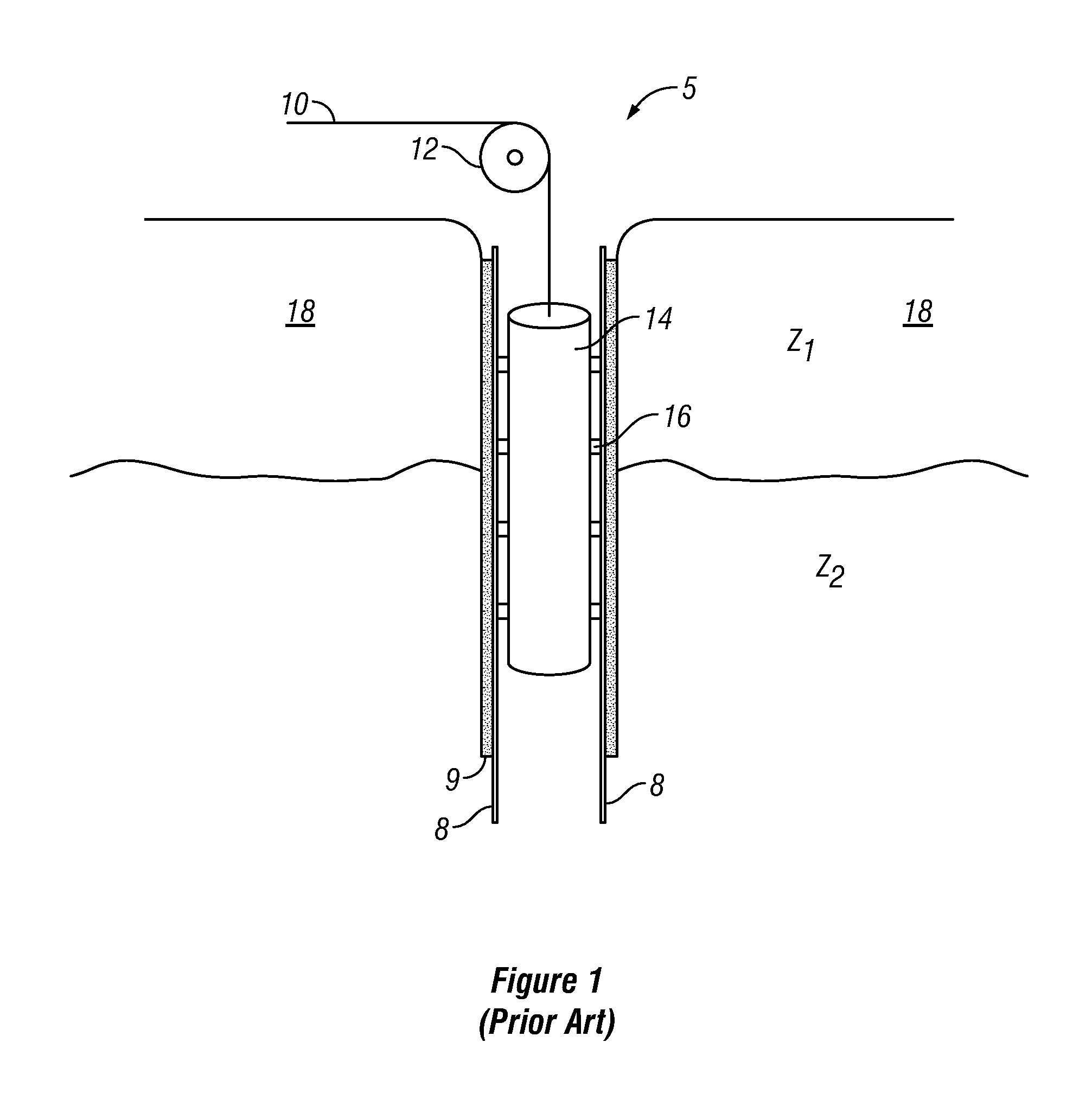
Should the cement 9 surrounding the casing 8 be defective and fail to provide isolation of the adjacent zones, water or other undesirable fluid can migrate into the hydrocarbon producing zone thus diluting or contaminating the hydrocarbons within the producing zone, and increasing production costs, delaying production or inhibiting resource recovery.
However, lower density fluids such as gas or air and high viscosity fluids such as some drilling mud may not provide adequate coupling between a piezoelectric device and the casing 8.
Furthermore, the presence of sludge, scale, or other like matter on the inner circumference of the casing 8 can detrimentally affect the efficacy of a bond log acquired with a piezoelectric device.
Another drawback faced when employing piezoelectric devices for use in bond logging operations involves the limitation of variant waveforms produced by these devices.
Fluids required to couple the wave from the transducer to the casing only conduct compressional waves, thus limiting the wave types that can be induced in or received from the casing.

Method used


Image

  • EMAT Acoustic Signal Measurement Using Modulated Gaussian Wavelet and Hilbert Demodulation
  • EMAT Acoustic Signal Measurement Using Modulated Gaussian Wavelet and Hilbert Demodulation
  • EMAT Acoustic Signal Measurement Using Modulated Gaussian Wavelet and Hilbert Demodulation

Examples


Embodiment Construction

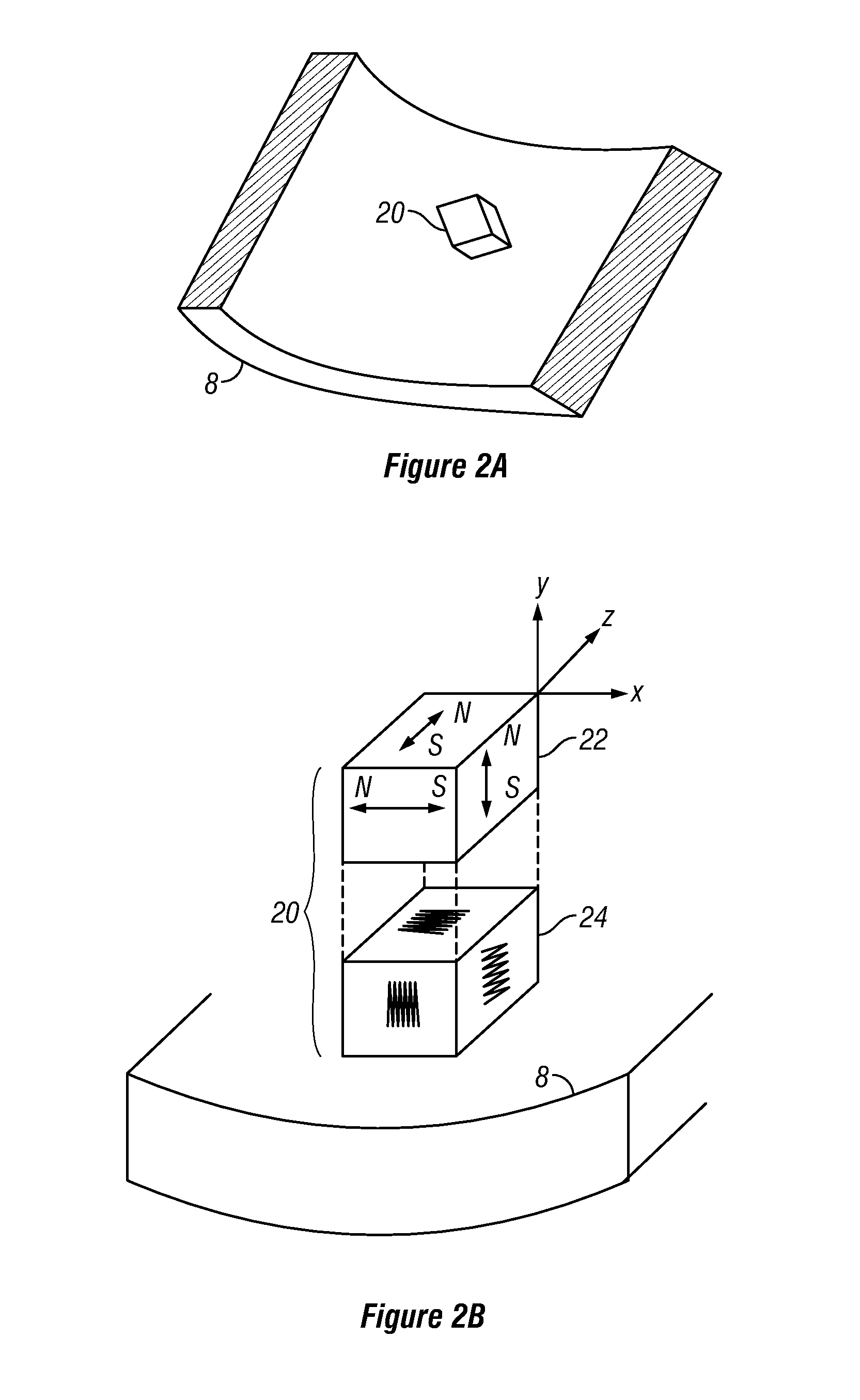
[0028]As illustrated in FIG. 2A, a magnetically coupled transducer 20 is positioned at any desired attitude proximate to a section of casing 8. For the purposes of clarity, only a portion of the length and diameter of a section of casing 8 is illustrated and the magnetically coupled transducer 20 is shown schematically in both FIG. 2A and FIG. 2B. The magnetically coupled transducer 20 may be positioned within the inner circumference of the tubular casing 8, but the magnetically coupled transducer 20 can also be positioned in other areas.

[0029]For any particular transducer 20, more than one magnet (of any type for example permanent, electro-magnetic, etc.) may be combined within a unit; such a configuration enables inducing various waveforms and facilitating measurement and acquisition of several waveforms. A transducer 20 capable of transmitting or receiving waveforms in orthogonal directions is schematically illustrated in FIG. 2B. While a schematic magnet 22 with orthogonal magne...


PUM


Abstract

Casing signals generated by an EMAT in a borehole are processed using at least two orthogonal band-limited filters. The band-limited filters may include Gaussian or Cauchy Wavelet filters. By using the Hilbert transform, an envelope of the filtered signals is determined and amplitudes and arrival times of individual arrivals are estimated. These can be used to estimate casing and cement properties.

Description

CROSS-REFERENCE TO RELATED APPLICATION[0001]This application is a continuation-in-part of U.S. patent application Ser. No. 12 / 268,110, filed Nov. 10, 2008, and claims the benefit of priority from the aforementioned application.FIELD OF THE DISCLOSURE[0002]The disclosure relates generally to the field of the evaluation of wellbore casing. More specifically the present disclosure relates to a method and apparatus to provide for the analysis of casing within a wellbore environment by producing and recording characteristics of waveforms traversing the casing and cement.BACKGROUND OF THE DISCLOSURE[0003]As illustrated in FIG. 1 wellbores typically comprise casing 8 set within the wellbore 5, where the casing 8 is bonded to the wellbore by adding cement 9 within the annulus formed between the outer diameter of the casing 8 and the inner diameter of the wellbore 5. The cement bond not only adheres to the casing 8 within the wellbore 5, but also serves to isolate adjacent zones (e.g. Z1 and...

Claims


Application Information

Patent Timeline
Patent Type & Authority Applications(United States)
IPC IPC(8): G01V1/40
CPCG01V1/44E21B47/0005E21B47/005
Inventor ZHAO, JINSONG
Owner BAKER HUGHES INC
Learn More