Likelihood value calculation device, likelihood value calculation method, and radio system

a technology of likelihood value calculation and likelihood value, which is applied in the direction of amplitude demodulation, coding, pulse technique, etc., can solve the problems of increased hardware amount, and large overhead of likelihood value calculation circuits

Active Publication Date: 2012-03-22
NEC CORP
View PDF5 Cites 8 Cited by
  • Summary
  • Abstract
  • Description
  • Claims
  • Application Information

AI Technical Summary

Benefits of technology

[0013]It is therefore an object of the present invention to provide a likelihood value calculation device, a likelihood value calculation method, and a radio system that can cope with a variety of radio modes and modulation modes in radio baseband processing and thereby provide a solution to the above-described problems.

Problems solved by technology

However, when the modulation types that are the object of discrimination become numerous, the amount of hardware increases to the same extent, giving rise to the problem of area overhead of the likelihood value calculation circuits.
In such cases, the amount of hardware is further increased, and the area overhead of the likelihood value calculation circuits also becomes great.
The transmission diversity described in Patent Document 2 is capable of dealing with changes in the bit assignment within the same modulation mode but encounters difficulties in coping with a variety of radio modes and modulation modes.
In order to cope with a variety of radio modes and modulation modes, a likelihood value calculation circuit must be provided for each of the above-described combinations, giving rise to the problem of increase in the amount of hardware and area overhead of the likelihood value calculation circuits.

Method used


Image

  • Likelihood value calculation device, likelihood value calculation method, and radio system
  • Likelihood value calculation device, likelihood value calculation method, and radio system
  • Likelihood value calculation device, likelihood value calculation method, and radio system

Examples


Embodiment Construction

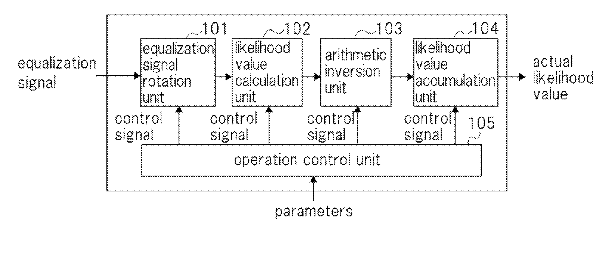
[0163]The configurations of each of equalization signal rotation unit 101, likelihood value calculation unit 102, arithmetic inversion unit 103, and likelihood value accumulation unit 104 that are used as parts of the likelihood value calculation device of FIG. 1 are next described as an actual working example.

[0164]The actual configuration of likelihood value calculation unit 102 is first described.

[0165]FIG. 14 shows an example of the configuration of the likelihood value calculation unit. This likelihood value calculation unit includes 64 QAM likelihood value calculation circuit 1500a, 8 PSK (b2) likelihood value calculation circuit 1500b, and selector 1516 that selects one of the output signals of these components. 8 PSK (b2) likelihood value calculation circuit 1500b is used when the likelihood value of bit b2 of 8 PSK modulation is to be found, and 64 QAM likelihood value calculation circuit 1500a is used when other likelihood values are to be found.

[0166]As shown in FIG. 14, ...


PUM


Abstract

A likelihood value calculation device includes: likelihood value calculation unit 201 that takes as input an equalization signal of a modulated signal, that, in accordance with a first control signal, calculates from the equalization signal that was received as input a provisional likelihood value for which the bit value of each signal point is “0” for each bit position; arithmetic inversion unit 202 that, in accordance with a second control signal, supplies for each bit position a provisional likelihood value without alteration that was supplied from likelihood value calculation unit 201 or subjects the provisional likelihood value that was supplied from likelihood value calculation unit 201 to arithmetic inversion and supplies the likelihood value following inversion; and operation control unit 200 that holds, for each combination of a radio mode and modulation mode, a control pattern that is used to control the operations of at least likelihood value calculation unit 201 and arithmetic inversion unit 202 and that generates the first and second control signals in accordance with the control pattern that is designated from among these control patterns.

Description

TECHNICAL FIELD[0001]The present invention relates to a likelihood value calculation device that calculates the likelihood value of a signal point based on constellation information in which the signal points (symbol data) of a digital modulated signal are mapped on a two-dimensional plane.BACKGROUND ART[0002]Normally, in radio baseband LSI (Large Scale Integration), an equalization process of a received baseband signal is carried out, likelihood values are calculated from the equalization signal that is obtained as a result, and a received signal is then created by performing error correction using the likelihood values that were calculated.[0003]When a likelihood value is calculated from an equalization signal, the calculation algorithm differs according to the modulation method. For example, modulation such as FSK (Frequency Shift-Keying), BPSK (Binary Phase-Shift Keying), QPSK (Quadrature Phase-Shift Keying), 8 PSK, 16 QAM (Quadrature Amplitude Modulation), and 64 QAM are freque...

Claims


Application Information

Patent Timeline
Patent Type & Authority Applications(United States)
IPC IPC(8): H03K5/159
CPCH03M13/25H04L27/34H04L25/067H03M13/6331
Inventor IGURA, HIROYUKI
Owner NEC CORP
Why Eureka
Try Eureka