
Method for optically scanning and measuring an environment

a technology applied in the field of optical scanning and measuring environment, can solve the problems of obscurity and cover the area behind, and achieve the effect of improving performan

Inactive Publication Date: 2012-03-22
FARO TECH INC
View PDF2 Cites 63 Cited by
  • Summary
  • Abstract
  • Description
  • Claims
  • Application Information

AI Technical Summary

Benefits of technology

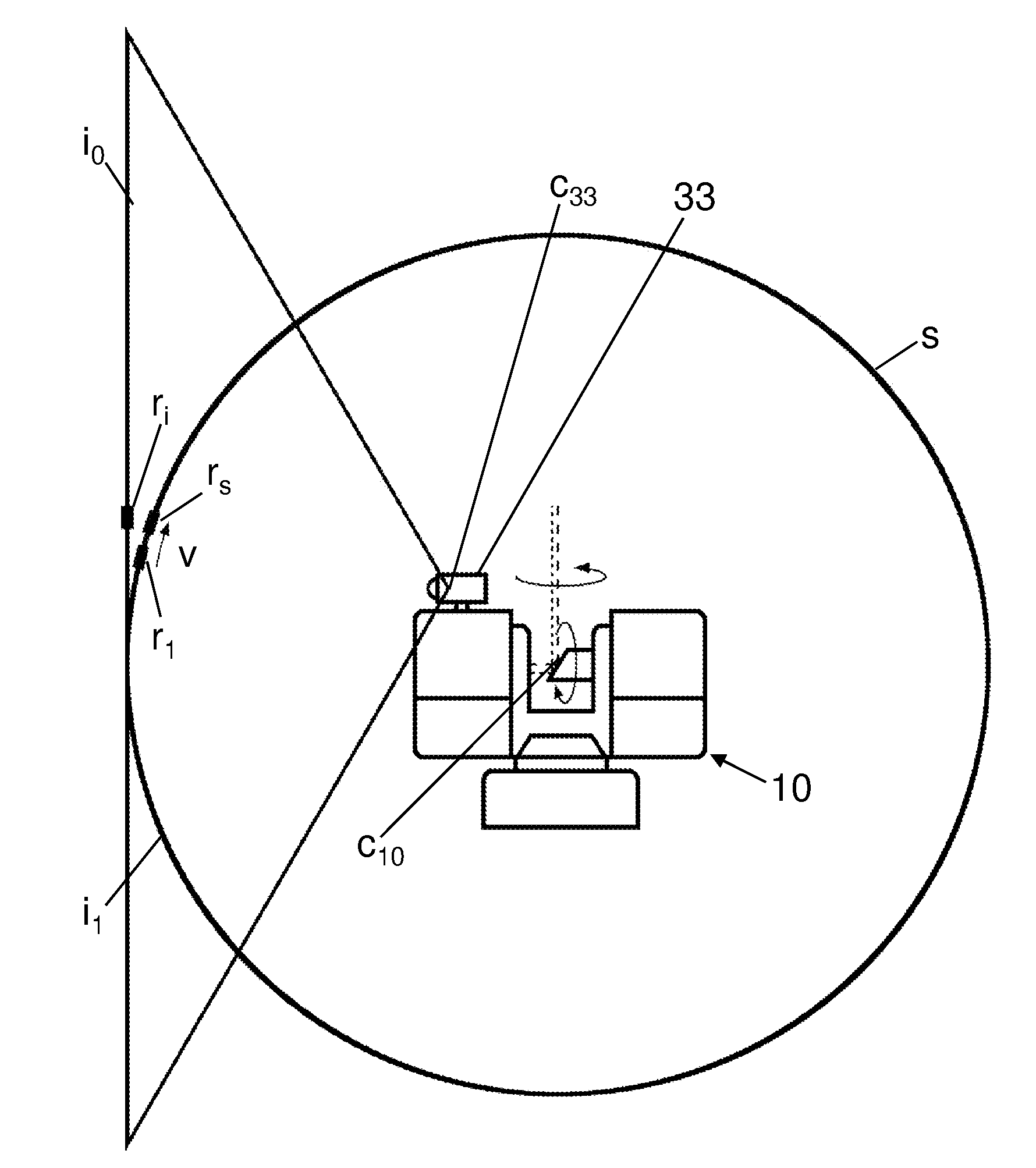
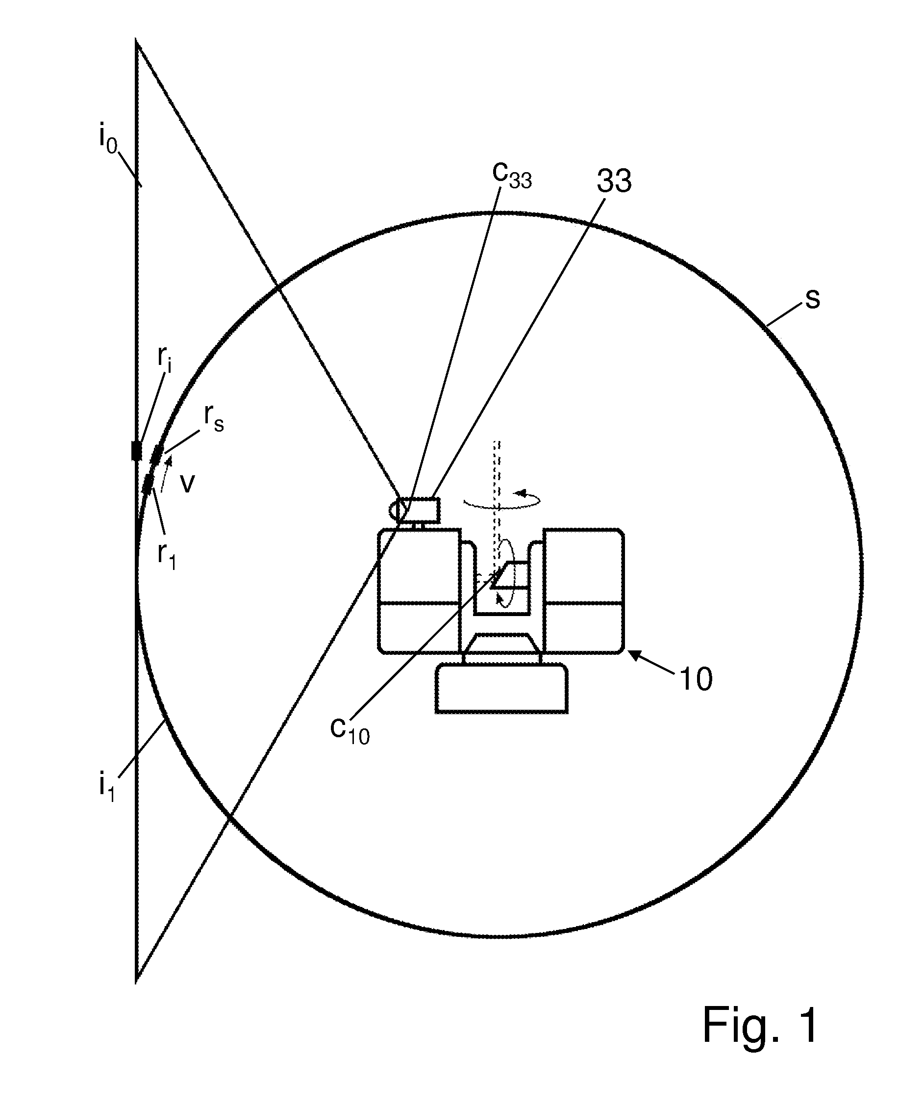
[0005]With a rough knowledge of camera position and orientation, which may be relative to the center and to the orientation of the laser scanner, which, however, is not sufficient for a direct link, the method according to embodiments of the present invention makes it possible to correct the deviations of the centers and their orientations by means of the control and evaluation unit and to link scan and color images. The color camera, instead of making a real movement, which strongly depends on mechanical precision, carries out just a virtual movement, i.e. a transformation of the color images. Correction is made iteratively for every single color image. Comparison between scan and color images takes place on a common projection screen which is taken as a reference surface. Provided that the color camera is mounted and dismounted, i.e. a certain distance to the laser scanner is established before the scan is made, or that it is moved by means of an adjustable holder, the method according to embodiments of the present invention corrects the resulting changes of position and orientation.
[0006]At first, compliance is provided only for the regions of interest of the corresponding color image with the corresponding regions of interest of the scan, thus improving performance. Regions of interest are those regions showing relatively large changes over a short distance and may be found automatically, for example by means of gradients. Alternatively, it is possible to use targets, i.e. check marks which, however, have the drawback of covering the area behind them.
[0009]Embodiments of the method of the present invention do not trust in simple gradient-based dynamics (as they are used according to known methods), as it starts iterations at different virtual camera positions and as it defines criteria of exclusion. Thus, the embodiments of the method of the present invention even work if secondary minima occur. Therefore, the embodiments of the method of the present invention are robust even in case of a large distance between laser scanner and color camera. Using regions of interest results in a higher performance and in a higher success of finding corresponding counterparts. Regions are eliminated (by the criteria of exclusion), for which it is difficult or impossible to find corresponding regions, e.g. when laser scanner and color camera see different images (due to different wave lengths). With respect to this, a classification of the regions of interest is helpful.

Problems solved by technology

Alternatively, it is possible to use targets, i.e. check marks which, however, have the drawback of covering the area behind them.

Method used


Image

  • Method for optically scanning and measuring an environment
  • Method for optically scanning and measuring an environment
  • Method for optically scanning and measuring an environment

Examples


Embodiment Construction

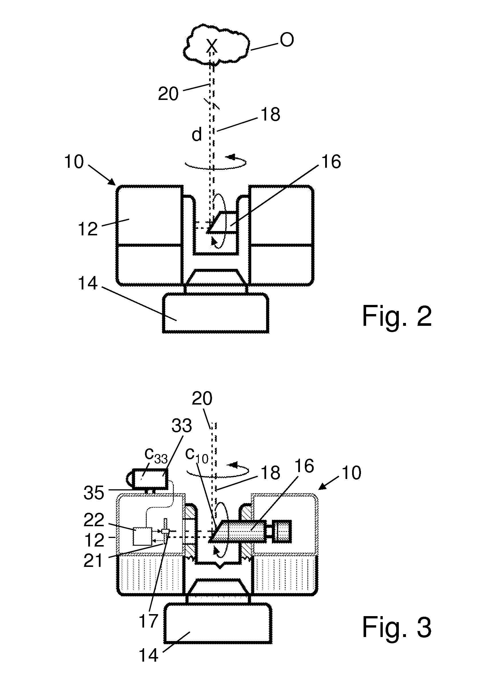
[0015]Referring to FIGS. 1-3, a laser scanner 10 is provided as a device for optically scanning and measuring the environment of the laser scanner 10. The laser scanner 10 has a measuring head 12 and a base 14. The measuring head 12 is mounted on the base 14 as a unit that can be rotated around a vertical axis. The measuring head 12 has a mirror 16, which can be rotated around a horizontal axis. The intersection point of the two rotational axes is designated center C10 of the laser scanner 10.

[0016]The measuring head 12 is further provided with a light emitter 17 for emitting an emission light beam 18. The emission light beam 18 may be a laser beam in the visible range of approx. 300 to 1000 nm wavelength, such as 790 nm. On principle, also other electro-magnetic waves having, for example, a greater wavelength can be used. The emission light beam 18 is amplitude-modulated, for example with a sinusoidal or with a rectangular-waveform modulation signal. The emission light beam 18 is e...


PUM


Abstract

With a method for optically scanning and measuring an environment by means of a laser scanner, which has a center, and which, for making a scan, optically scans and measures its environment by means of light beams and evaluates it by means of a control and evaluation unit, wherein a color camera having a center takes colored images of the environment which must be linked with the scan, the control and evaluation unit of the laser scanner, to which the color camera is connected, links the scan and the colored images and corrects deviations of the center and / or the orientation of the color camera relative to the center and / or the orientation of the laser scanner by virtually moving the color camera iteratively for each colored image and by transforming at least part of the colored image for this new virtual position and / or orientation of the color camera, until the projection of the colored image and the projection of the scan onto a common reference surface comply with each other in the best possible way.

Description

CROSS REFERENCE TO RELATED APPLICATIONS[0001]The present application is a National Stage Application of PCT Application No. PCT / EP2010 / 001780 filed on Mar. 22, 2010, which claims the benefit of U.S. Provisional Patent Application No. 61 / 299,586 filed on Jan. 29, 2010, and of pending German Patent Application No. DE 10 2009 015 921.5, filed on Mar. 25, 2009, and which are hereby incorporated by reference.BACKGROUND OF THE INVENTION[0002]The invention relates to a method for optically scanning and measuring an environment.[0003]By means of a laser scanner such as is known for example from DE 20 2006 005 643, the environment of a laser scanner can be optically scanned and measured by means of a laser scanner. For gaining additional information, a camera, which takes RGB signals, is mounted on the laser scanner, so that the measuring points of the scan can be completed by color information. The camera holder is rotatable. To avoid parallax errors, the camera, for taking its records, is ...

Claims


Application Information

Patent Timeline
IPC IPC(8): G06K9/34H04N7/18G01S17/86G01S17/89
CPCG01C15/002G01S17/89G01S17/42G01S17/023G01S17/86
Inventor OSSIG, MARTINBOGICEVIC, IVANBUCKING, NORBERT
Owner FARO TECH INC
Learn More