Acoustic-assisted iterative wave form optimization for deep tissue focusing

a technology of deep tissue and iterative wave form, applied in the field of deep tissue iterative wave form optimization, can solve the problems of tissue damage, impracticality and unsafe, and scattering of light in the tissue, and achieve the effects of improving the efficiency of deep tissue focusing

Active Publication Date: 2012-03-22
CALIFORNIA INST OF TECH
View PDF23 Cites 60 Cited by
  • Summary
  • Abstract
  • Description
  • Claims
  • Application Information

AI Technical Summary

Benefits of technology

[0029]One or more embodiments of the present invention disclose an apparatus for performing one or more embodiments of the method. The apparatus can comprise means for generating and transmitting an field (e.g., acoustic field) that controllably defines one or more targets within the sample (e.g., an acoustic wave source and control system); (b) means for irradiating the sample with input EM radiation having an input wavefront (e.g., an EM radiation source, such as a laser, light emitting device, and a control system, such as an imaging/focusing lens system); (c) a detection system or means, for detectin...

Problems solved by technology

However, despite the impressive progress in the field of optics, tissue scattering of light presents a major road block in applying these optical methods in deep tissues.
This eventually leads to tissue damage and is therefore impractical and unsafe.
Although several methods to overcome the problem of tissue scattering have been proposed, these methods are only able to refocus light through a piece of tissue, but not controllably within the tissue.
It is apparent that this method has yet to address several impediments that prevent its direct application to biomedical appl...

Method used


Image

  • Acoustic-assisted iterative wave form optimization for deep tissue focusing
  • Acoustic-assisted iterative wave form optimization for deep tissue focusing
  • Acoustic-assisted iterative wave form optimization for deep tissue focusing

Examples


Embodiment Construction

[0044]In the following description, reference is made to the accompanying drawings which form a part hereof, and which is shown, by way of illustration, several embodiments of the present invention. It is understood that other embodiments may be utilized and structural changes may be made without departing from the scope of the present invention.

[0045]Overview

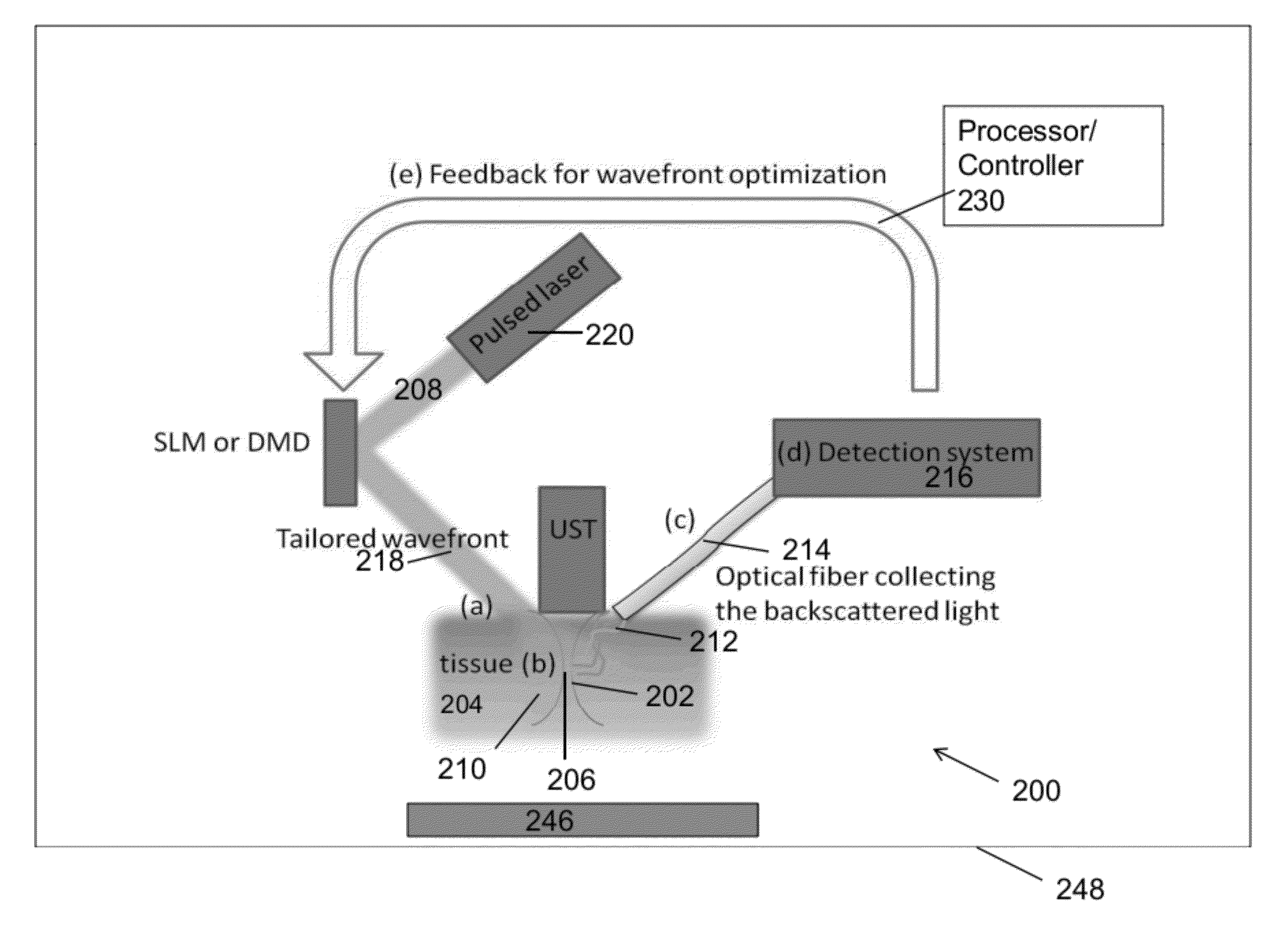
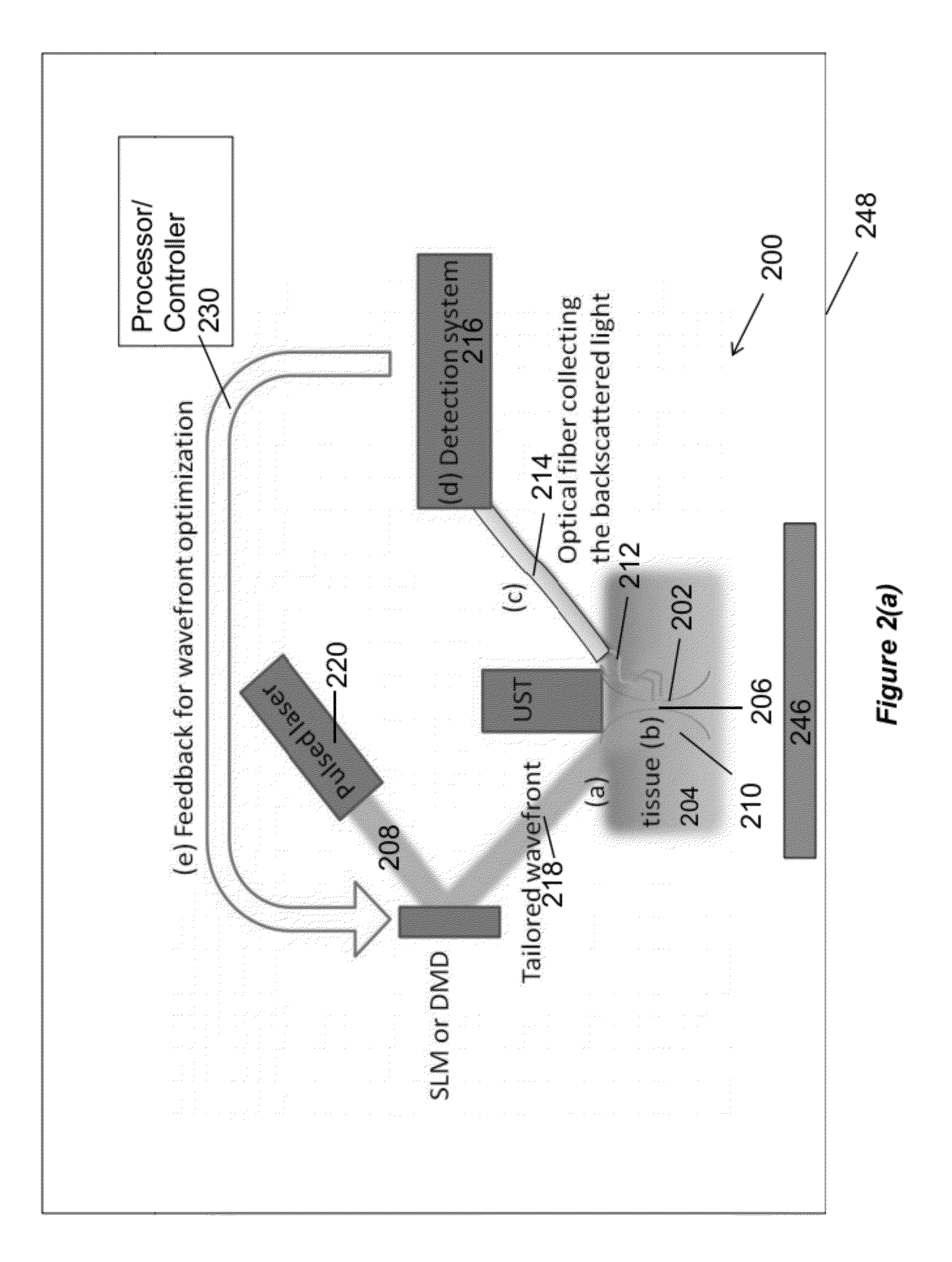
[0046]In the proposed method of one or more embodiments of the present invention, a high frequency ultrasound transducer is used to define an ultrasound focus within a tissue. Light that passes through the ultrasound focus is frequency-shifted. Several methods, including digital holography [2] and confocal fabry perot interferometer [3], can be used to detect the frequency-shifted light. By detecting the amount of frequency-shifted light as a feedback, the input wavefront is iteratively tailored using a SLM or a deformable mirror device, such that the resulting wavefront comes to a tight focus at the ultrasound focus. In other ...


PUM


Abstract

A method, apparatus, and article of manufacture for irradiating one or more targets within a sample with electromagnetic (EM) radiation. One or more targets within the sample are controllably defined with an acoustic field. The sample is irradiated with input EM radiation having an input wavefront. An amount of frequency shifted EM radiation is detected, wherein at least some of the input EM radiation that passes through the acoustic field at the targets is shifted in frequency to form the frequency shifted EM radiation. The input wavefront is modified, using feedback comprising the amount of the frequency shifted EM radiation that is detected, into a modified wavefront. The sample is irradiated using the input EM radiation comprising the modified wavefront, and the process is repeated as desired.

Description

CROSS-REFERENCE TO RELATED APPLICATIONS[0001]This application claims the benefit under 35 U.S.C. Section 119(e) of the following co-pending and commonly-assigned U.S. provisional patent application(s), which is / are incorporated by reference herein:[0002]Provisional Application Ser. No. 61 / 384,660, filed on Sep. 20, 2010, by Ying Min Wang and Changhuei Yang, entitled “ACOUSTIC-ASSISTED ITERATIVE WAVE FORM OPTIMIZATION FOR DEEP TISSUE FOCUSING,” attorneys' docket number 176.66-US-P1 (CIT-5694-P).[0003]This application is related to the following co-pending and commonly-assigned patent applications, which applications are incorporated by reference herein:[0004]1. U.S. Utility patent application Ser. No. 12 / 886,320, filed on Sep. 20, 2010, by Zahid Yaqoob, Emily McDowell and Changhuei Yang, entitled “OPTICAL PHASE PROCESSING IN A SCATTERING MEDIUM,” attorney's docket number 176.54-US-D1, which application is a divisional of U.S. Utility patent application Ser. No. 11 / 868,394, filed on O...

Claims


Application Information

Patent Timeline
IPC IPC(8): C12Q3/00C12M1/42
CPCA61B5/0059G01N21/47G01N2021/4709G01N21/65G01N21/49G01N21/1717G01N2021/1727
Inventor WANG, YING MINYANG, CHANGHUEI
Owner CALIFORNIA INST OF TECH
Why Eureka
Try Eureka