Control apparatus for vehicular power transmitting system

a control apparatus and transmission system technology, applied in the direction of machines/engines, electric devices, process and machine control, etc., can solve the problems of shifting shock, operation in clutch free state may have a risk of an increase of shifting shock, etc., to reduce shifting shock, reduce the risk of shifting shock, and facilitate implementation

Active Publication Date: 2012-03-22
TOYOTA JIDOSHA KK
View PDF10 Cites 60 Cited by
  • Summary
  • Abstract
  • Description
  • Claims
  • Application Information

AI Technical Summary

Benefits of technology

[0018]Preferably, the above-described transmission portion is a step-variable transmission having speed ratios to be mechanically established. In this practical arrangement of the vehicular power transmitting system provided with the step-variable transmission (transmission portion) having a plurality of shift positions to be established in steps, the control apparatus implements the shifting control to perform the shifting operation of the transmission portion when it is determined that the input torque of the transmission portion is substantially zero, so that the amount of change of the input torque of the transmission portion in the shifting operation is reduced to reduce the shifting shock of the transmission portion.
[0010]The control apparatus is preferably configured to provide a predetermined value of the above-described regenerative torque used to determine whether the input torque of the above-described transmission portion is substantially zero, and to determine whether the input torque of the above-described transmission portion is substantially zero, by determining whether the regenerative torque is equal to the predetermined value. Thus, the determination as to whether the input torque of the transmission portion is substantially zero can be adequately made, and the shifting operation of the transmission portion is performed when the input torque is substantially zero.

Problems solved by technology

During the coasting run wherein a regenerative torque of the electric motor is input to the transmission portion, a shifting operation of the transmission portion while the regenerative torque of the electric motor is input thereto may possibly cause a shifting shock.
However, the shifting operation in the clutch free states may have a risk of an increase of the shifting shock where the input torque of the transmission portion is large, since the input torque transmitted to the output side of the transmission portion is increased in steps upon completion of the shifting operation effected by termination of the clutch free states.
If the above-indicated point of the vehicle running speed at which the coasting shift-down operation is performed is fixed, the input torque of the transmission portion upon the shift-down operation may vary depending upon the operation amount of the brake operating member, giving rise to a risk of an increase of the shifting shock due to an increase of the output torque of the transmission portion upon completion of the shift-down operation.
In this respect, it is noted that the problem described above is not known in the art, and it has not yet been proposed to perform a coasting shift-down operation of the transmission portion at an adequate timing so as to reduce the shifting shock.

Method used


Image

  • Control apparatus for vehicular power transmitting system
  • Control apparatus for vehicular power transmitting system
  • Control apparatus for vehicular power transmitting system

Examples


embodiment 1

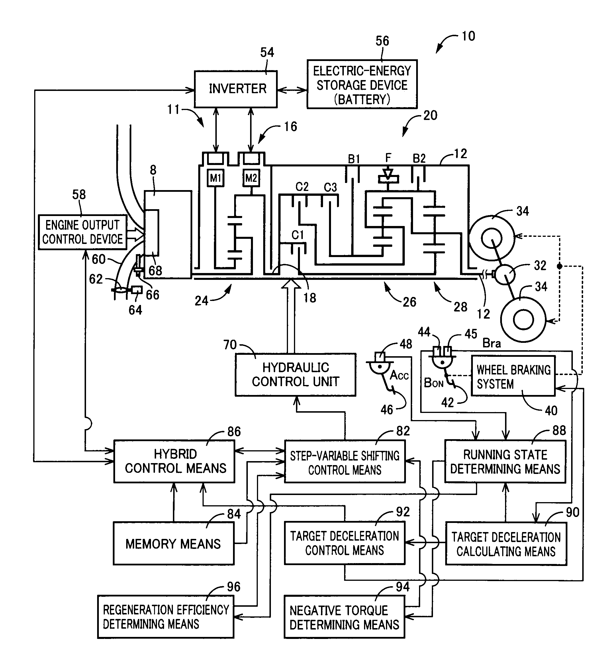
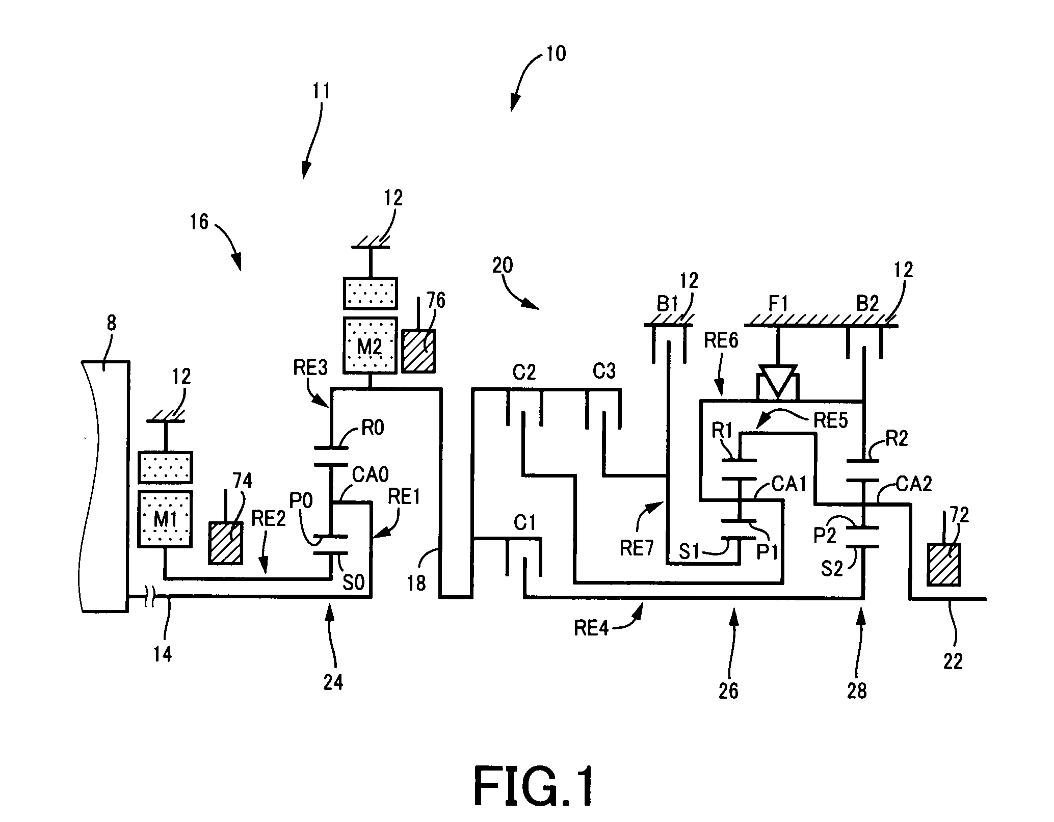
[0038]FIG. 1 is the schematic view showing a vehicular power transmitting system 10 (hereinafter referred to as “power transmitting system 10”) to which the control apparatus according to the present invention is applicable. This power transmitting system 10 is suitably used for a hybrid vehicle. As shown in FIG. 1, the power transmitting system 10 includes: an input rotary member in the form of an input shaft 14; a continuously-variable transmission portion in the form of a differential portion 11 connected to the input shaft 14 either directly, or indirectly via a pulsation absorbing damper (vibration damping device) not shown; a power transmitting portion in the form of an automatic transmission portion 20 disposed in a power transmitting path between the differential portion 11 and drive wheels 34 (shown in FIG. 7) and connected in series via a power transmitting member 18 to the differential portion 11 and the drive wheels 34; and an output rotary member in the form of an outpu...

embodiment 2

[0110]In the preceding embodiment, the determination as to whether the input torque TIN of the automatic transmission portion 20 is zero is made on the basis of the determination as to whether the regenerative torque of the second electric motor M2 is equal to the predetermined value. In the present embodiment, the determination as to whether the input torque TIN of the automatic transmission portion 20 is zero or not is made on the basis of a determination as to whether a point representative of the actual running state of the vehicle coincides with a predetermined shifting point at which the shifting operation of the automatic transmission portion 20 should be performed while the input torque TIN of the automatic transmission portion 20 is zero. Namely, a coasting shift-down point at which the coasting shift-down operation of the automatic transmission portion 20 should be performed while the input torque TIN of the automatic transmission portion 20 is zero is predetermined so tha...


PUM


Abstract

A control apparatus for a power transmitting system of a vehicle provided with a transmission portion having a plurality of speed ratios to be established in steps, and an electric motor operatively connected to an input-side rotary member of said transmission portion and controlled to generate a regenerative torque in a decelerating state of the vehicle, the control apparatus is configured: to implement a shifting control to perform a shifting operation of said transmission portion under the condition of a determination in the decelerating state of the vehicle that an input torque of said transmission portion including said regenerative torque is substantially zero; and to implement the shifting control to perform the shifting operation of said transmission portion under the condition of an improvement of a fuel economy rather than the determination that the input torque of said transmission portion is substantially zero, when a target deceleration value of the vehicle is larger than a predetermined threshold value.

Description

TECHNICAL FIELD[0001]The present invention relates to a control apparatus for a vehicular power transmitting system provided with an electric motor operatively connected to an input-side rotary member of a transmission portion, and more particularly to techniques for applying a braking force to a vehicle by implementing a regenerative control of the electric motor during a coasting run of the vehicle.BACKGROUND ART[0002]There is well known a power transmitting system of a vehicle provided with an electric motor operatively connected to an input-side rotary member of a transmission portion. Patent Documents 1 and 2 disclose examples of such a vehicular power transmitting system. In the vehicular power transmitting system disclosed in the Patent Document 1, the transmission portion is shifted according to predetermined shifting lines representative of variables in the form of an required vehicle output amount (such as an accelerator operation amount or a required output torque) and a ...

Claims


Application Information

Patent Timeline
Patent Type & Authority Applications(United States)
IPC IPC(8): B60W20/00B60K6/445B60K6/547B60L7/24B60W10/08B60W10/10B60W10/18F02D29/00F02D29/02F16H59/14F16H59/54F16H61/04F16H61/21F16H61/68F16H61/684F16H61/686F16H63/40F16H63/50
CPCB60K1/02Y02T10/7275B60K6/445B60K6/547B60L7/14B60L11/123B60L11/14B60L15/2027B60L2220/14B60L2240/423B60L2240/486B60L2270/145B60W10/08B60W10/115B60W20/00B60W30/18072B60W30/19B60W2710/083B60W2710/1022B60W2710/1055F16H61/0437F16H2037/0873Y02T10/6217Y02T10/6239Y02T10/642Y02T10/7077B60Y2300/18066F16H2059/186F16H2061/0237B60Y2300/18125B60K6/365Y02T10/72B60L50/61B60L50/16Y02T10/62Y02T10/64Y02T10/60Y02T10/7072Y02T10/70B60W10/10B60W20/30B60W2510/1025
Inventor MINAMIKAWA, KOKIANDO, YOSHIKI
Owner TOYOTA JIDOSHA KK
Why Eureka
Try Eureka