Valve actuator control system and method of use

a valve actuator and control system technology, applied in the direction of machines/engines, water supply installation, positive displacement liquid engines, etc., can solve the problems of dangerously high pressure on the area surrounding the wellhead system and the wellhead valve, and require manual operation to open and close the valv

Active Publication Date: 2012-03-29
SAFOCO
View PDF12 Cites 50 Cited by
  • Summary
  • Abstract
  • Description
  • Claims
  • Application Information

AI Technical Summary

Benefits of technology

[0008]In one embodiment, a valve actuator control system for use with a valve actuator may comprise a first and second pump assembly; a first and second control valve assembly; a fluid reservoir in communication with the pump assemblies and the control valve assemblies; and a controller assembly operable to actuate the pump assemblies to direct fluid from the fluid reservoir to the valve actuator, and operable to actuate the control valve assemblies to direct fluid from the valve actuator to the fluid reservoir.
[0009]In one embodiment, a method of actuating a valve actuator using a valve actuator control system may comprise injecting pressurized fluid from a fluid reservoir of the valve actuator control system into a first chamber of the valve actuator; discharging pressurized fluid from a second chamber of the valve actuator into the fluid reservoir; and actuating the valve actuator from a first position to a second position.

Problems solved by technology

These valves may be physically located miles apart from each other and may require manual operation to open and close the valves.
An extensive amount of time and energy is required to direct and re-direct fluid through the pipeline system using manually operated valves.
During the fracturing operation, the area surrounding the wellhead system and the wellhead valves may be subjected to dangerously high levels of pressure.
Remote communications may be limited or restricted in the operating field during such type of wellbore operations, thereby requiring manual operation of the wellhead valves and subjecting the valve operators to the dangerous environment.

Method used


Image

  • Valve actuator control system and method of use
  • Valve actuator control system and method of use
  • Valve actuator control system and method of use

Examples


Embodiment Construction

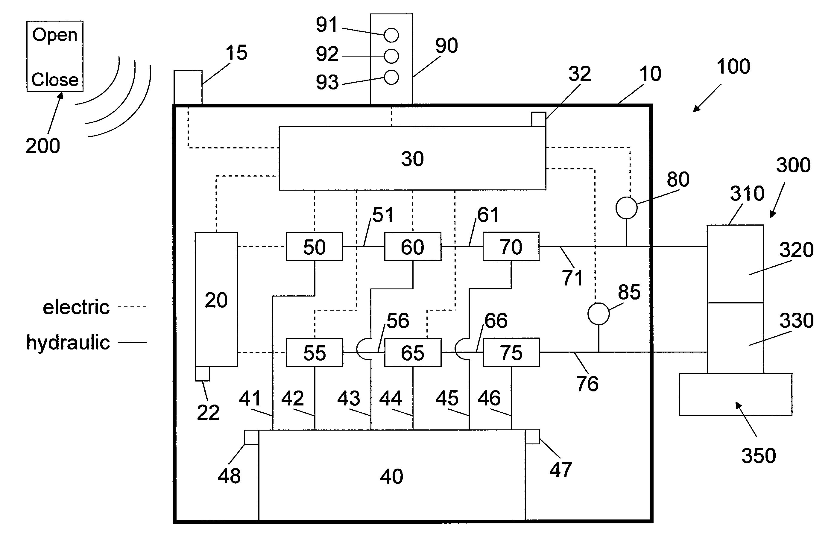
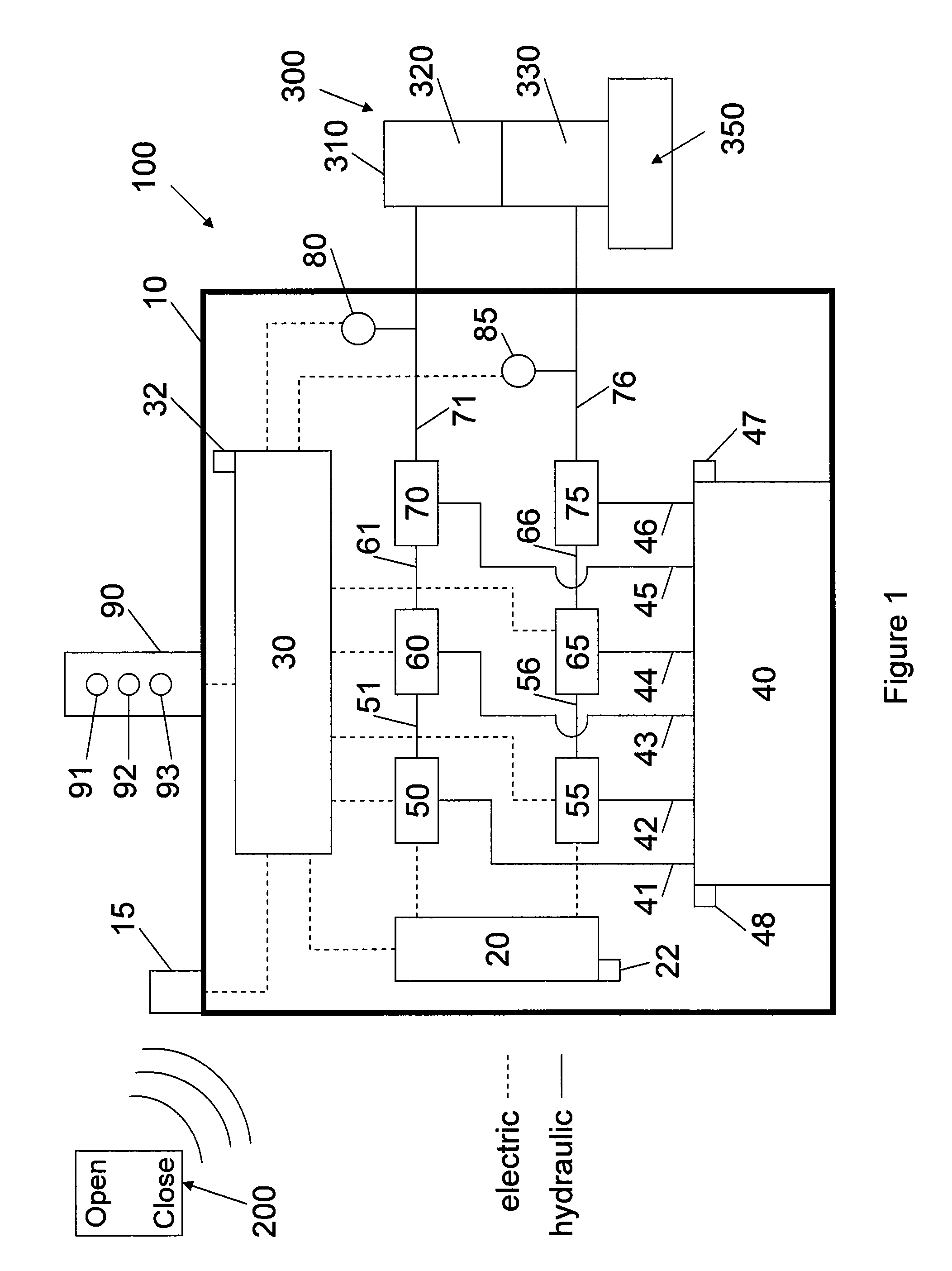
[0015]FIG. 1 illustrates a valve actuator control system 100 for a valve actuator 300 according to one embodiment. The valve actuator control system 100 may be remotely operated via a remote control device 200 to actuate the valve actuator 300 to open and close a valve 350 that is connected to the valve actuator 300. Hydraulic fluid may be supplied from that valve actuator control system 100 to the valve actuator 300 to actuate the valve 350 upon receiving a signal from an operator via the remote control device 200 at a location remote from the valve 350.

[0016]The valve actuator control system 100 may be “self-contained,” which means that it does not depend on any external pneumatic, hydraulic, mechanical, or electrical sources for its operation to actuate the valve actuator 300, with limited exception depending on various embodiments. One exception including a signal sent to the controller assembly 30 via the remote control device 200 and the receiver 15. Another exception includin...


PUM


Abstract

A valve actuator control system for use with a valve actuator may include two pump assemblies, two control valve assemblies, two transducers, a fluid reservoir, and a controller assembly. The controller assembly may actuate the pump assemblies to direct fluid from the fluid reservoir to the valve actuator, and may actuate the control valve assemblies to direct fluid from the valve actuator to the fluid reservoir. A method of actuating a valve actuator using a valve actuator control system may comprise sending a signal to the valve actuator control system, injecting pressurized fluid from a fluid reservoir of the valve actuator control system into a first chamber of the valve actuator, discharging pressurized fluid from a second chamber of the valve actuator into the fluid reservoir, and actuating the valve actuator from a first position to a second position.

Description

CROSS-REFERENCE TO RELATED APPLICATIONS[0001]This application claims benefit of U.S. provisional patent application Ser. No. 61 / 384,145, filed Sep. 17, 2010; U.S. provisional patent application Ser. No. 61 / 497,470, filed Jun. 15, 2011; and U.S. provisional patent application Ser. No. 61 / 497,828, filed Jun. 16, 2011. Each of these applications is incorporated herein by reference in its entirety.BACKGROUND OF THE INVENTION[0002]1. Field of the Invention[0003]Embodiments of the invention generally relate to systems and methods for controlling a valve from a remote location. Particularly, embodiments of the invention relate to a self-contained control system for hydraulically actuating a valve actuator, the self-contained control system operable via a remote control device. More particularly, embodiments of the invention relate to a remotely operated, self-contained control system for operating a double acting hydraulic valve actuator to open and close a valve.[0004]2. Description of th...

Claims


Application Information

Patent Timeline
Patent Type & Authority Applications(United States)
IPC IPC(8): E03B11/16F17D3/00
CPCF04B23/00F04B49/03F16K37/0041F16K31/42F15B20/00Y10T137/0324Y10T137/85978
Inventor LYMBEROPOULOS, DAVID
Owner SAFOCO
Why Eureka
Try Eureka