Eureka AIR delivers breakthrough ideas for toughest innovation challenges, trusted by R&D personnel around the world.

Sensor used together with a detector to measure biomaterial, and apparatus using same

Inactive Publication Date: 2012-03-29
CERAGEM MEDISYS
View PDF10 Cites 8 Cited by
  • Summary
  • Abstract
  • Description
  • Claims
  • Application Information

AI Technical Summary

Benefits of technology

[0012]According to the present invention, a biomaterial measuring apparatus in accordance with the present invention can be easily used by a user with poor vision. In addition, the biomaterial measuring apparatus in accordance with the present invention can minimize contamination of a sensor from the outside.

Problems solved by technology

In contrast, the optical biosensors have a disadvantage in that they require a longer measurement time and a greater quantity of samples than the electrochemical biosensors.
Further, the optical biosensors have other disadvantages in that measured results are influenced by turbidity of a sample, and it is difficult to miniaturize an optical unit.
However, the electrochemical biosensors have disadvantages in that an electrode manufacturing process is additionally required, the cost of production is high, and a measured signal is very sensitive to response time.
However, for example, since many diabetic and elderly patients have poor vision, it is difficult to insert the biosensor having a planar strip structure into the narrow slit.
In addition, when the biosensor is removed from the detector after measurement of the blood sugar, the user grips around a portion of the biosensor stained with the blood and extracts and wastes the biosensor.
At this time, since the user's finger is likely to be stained with blood, the user may feel uncomfortable.
In addition, the conventional strip type biosensor may be easily contaminated when the biosensor is inserted into the detector by the user.

Method used


Image

  • Sensor used together with a detector to measure biomaterial, and apparatus using same
  • Sensor used together with a detector to measure biomaterial, and apparatus using same
  • Sensor used together with a detector to measure biomaterial, and apparatus using same

Examples


Embodiment Construction

[0024]The objects, features, and advantages of the present invention will be apparent from the following detailed description of embodiments of the invention with references to the following drawings. Descriptions of well-known components and processing techniques are omitted so as not to unnecessarily obscure the embodiments of the present invention. The following terms are defined in consideration of functions of the to present invention and may be changed according to users or operator's intentions or customs. Thus, the terms shall be defined based on the contents described throughout the specification. Hereinafter, embodiments of the present invention will be described in detail with reference to the accompanying drawings.

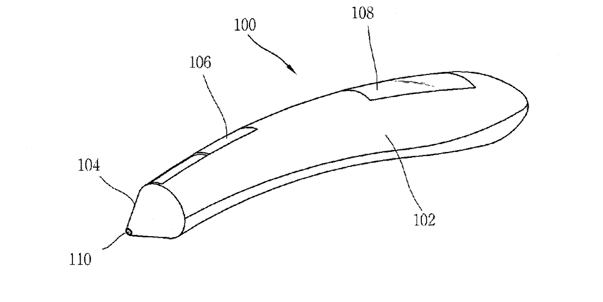
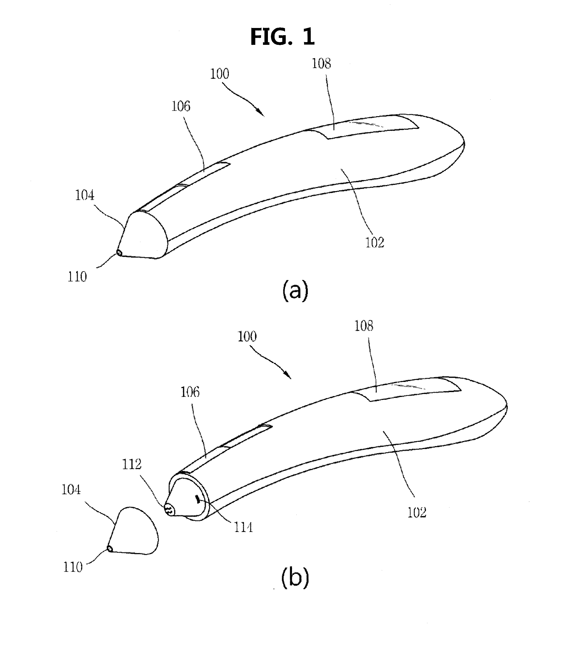
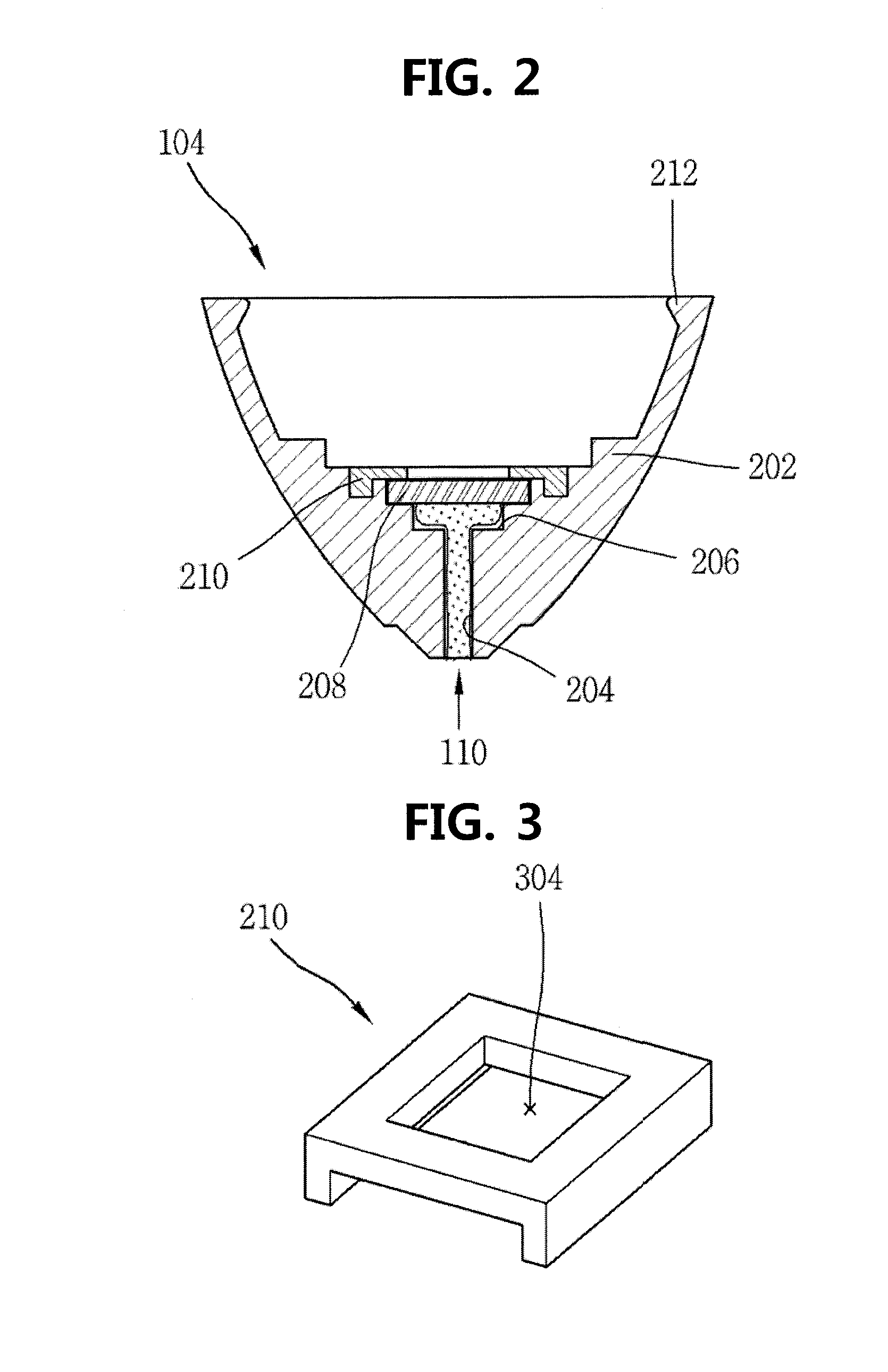
[0025]FIG. 1A is a view for explaining a biomaterial measuring apparatus in accordance with an embodiment of the present invention, and FIG. 1B is a view for explaining a state in which a biosensor is detached from a detector of the biomaterial measuring appara...


PUM

PropertyMeasurementUnit
Forceaaaaaaaaaa
Structureaaaaaaaaaa
Shapeaaaaaaaaaa

Abstract

The present invention relates to a sensor used together with a detector to measure biomaterial, and to an apparatus using same. A sensor of the present invention comprises: a body portion with a three-dimensional shape, having a biomaterial introduction hole, and attachable and detachable to / from a detector; a sensor portion with a plurality of reaction electrodes formed on one surface thereof, and a plurality of transfer electrodes formed on the other surface thereof; and an analyzer reagent fixed above the reaction electrodes. The sensor portion, together with the body portion, forms a reaction chamber connected to the biomaterial introduction hole, and is attached to the body portion such that the reaction electrodes are oriented toward the reaction chamber. According to the present invention, attachment and detachment is easy, even for the elderly, and the contamination of the sensor can be minimized.

Description

TECHNICAL FIELD[0001]The present invention relates to a sensor used with a detector to measure a biomaterial and an apparatus using the same, and more particularly, a biomaterial measuring sensor and a measuring apparatus using the same that are capable of enabling easy attachment and detachment even when a user with poor vision or mobility uses the sensor and minimizing contamination of the sensor.BACKGROUND ART[0002]A biosensor is a measuring apparatus for investigating properties of a material using functions of an organism. Since the biosensor uses a biomaterial as a detection element, sensitivity and reaction specificity are good. Accordingly, the biosensor is widely used in various fields such as clinical chemistry assay of medical / medicine fields, process measurement of bio industries, environment measurement, stability estimation of chemicals, and so on, and its range is being continuously enlarged. In particular, in a medicine diagnosis field, the biosensors are widely used...

Claims


Application Information

Patent Timeline
IPC IPC(8): G01N27/327G01N27/416
CPCG01N27/3272G01N33/483
Inventor LEE, JIN-WOOCHOI, JAE-KYUKIM, TAE-HUNYOON, YOUNG-IL
Owner CERAGEM MEDISYS
Why Eureka
Eureka Blog
Learn More