Consumable electrode arc welding method and consumable electrode arc welding device

a consumable electrode and arc welding technology, which is applied in the direction of welding/cutting media/materials, welding apparatus, manufacturing tools, etc., can solve the problems of unstable arc state, decrease in welding temperature of welded portion, and increase the risk of arc arc arc instability, etc., to achieve uniform beading, enhance welding stability, and reduce the effect of sputter

Active Publication Date: 2012-03-29
PANASONIC CORP
View PDF12 Cites 55 Cited by
  • Summary
  • Abstract
  • Description
  • Claims
  • Application Information

AI Technical Summary

Benefits of technology

[0019]With the above structure, spatter can be reduced and uniform bead can be achieved by controlling the wire feed speed, even if any external disturbance, such as change of distance between the tip and base material, occurs during arc generation. Accordingly, stability of arc can be enhanced.

Problems solved by technology

This may become spatter and may splatter out of a weld pool.
As a result, the state of unstable arc has occurred.
In this case, temperature of a welded portion decreases, and weld bead narrows and thins due to extended short circuit time.
This may result in uneven bead width.
In addition, welding may become not feasible due to deposited wire end and base material.
In any case, spatter generation increases, and the bead width becomes uneven.
The average feed speed of wire feed speed, short circuit cycle, and the number of short circuits become unstable and change if the arc phenomenon changes.
Welding results thus cannot be stabilized.
However, external disturbance such as change of distance between the tip and base material typically due to deviation in placement of base material or variations in accuracy of components, such as pressed components, frequently occur at actual production sites.
Accordingly, the average feed speed of wire feed speed and short circuit cycle greatly change and fluctuate, resulting in difficulty to stabilize welding results.

Method used


Image

  • Consumable electrode arc welding method and consumable electrode arc welding device
  • Consumable electrode arc welding method and consumable electrode arc welding device
  • Consumable electrode arc welding method and consumable electrode arc welding device

Examples


first exemplary embodiment

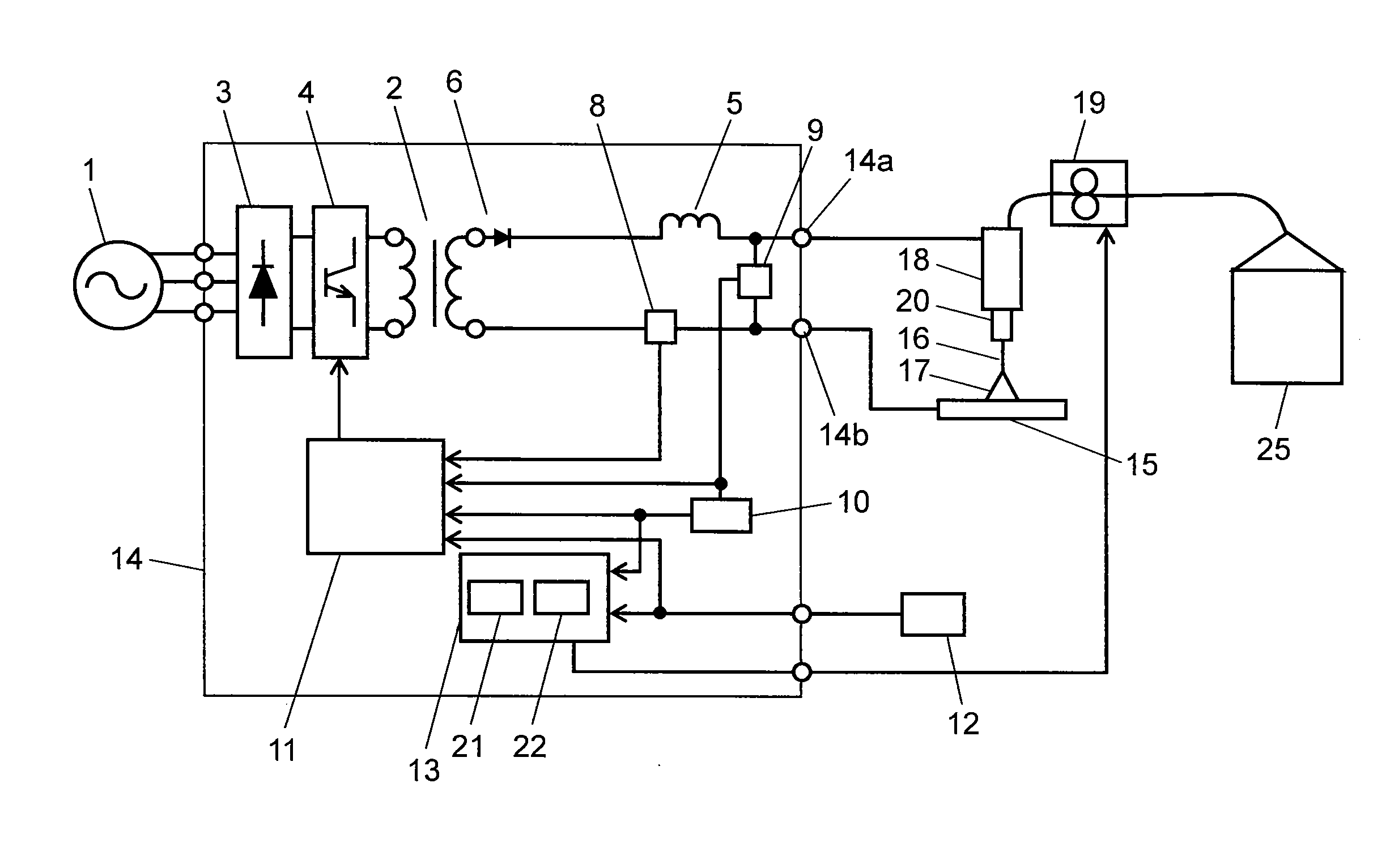
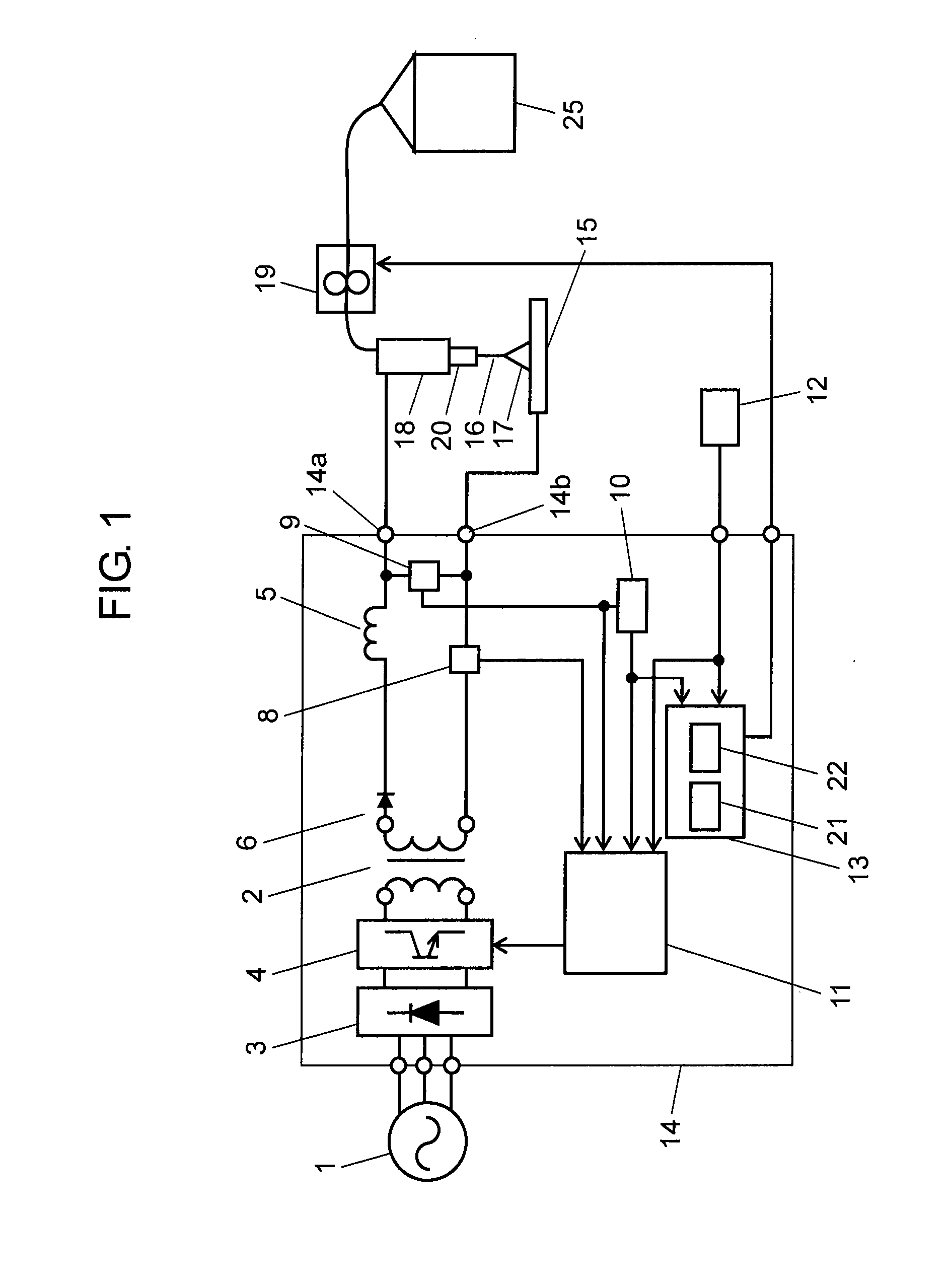
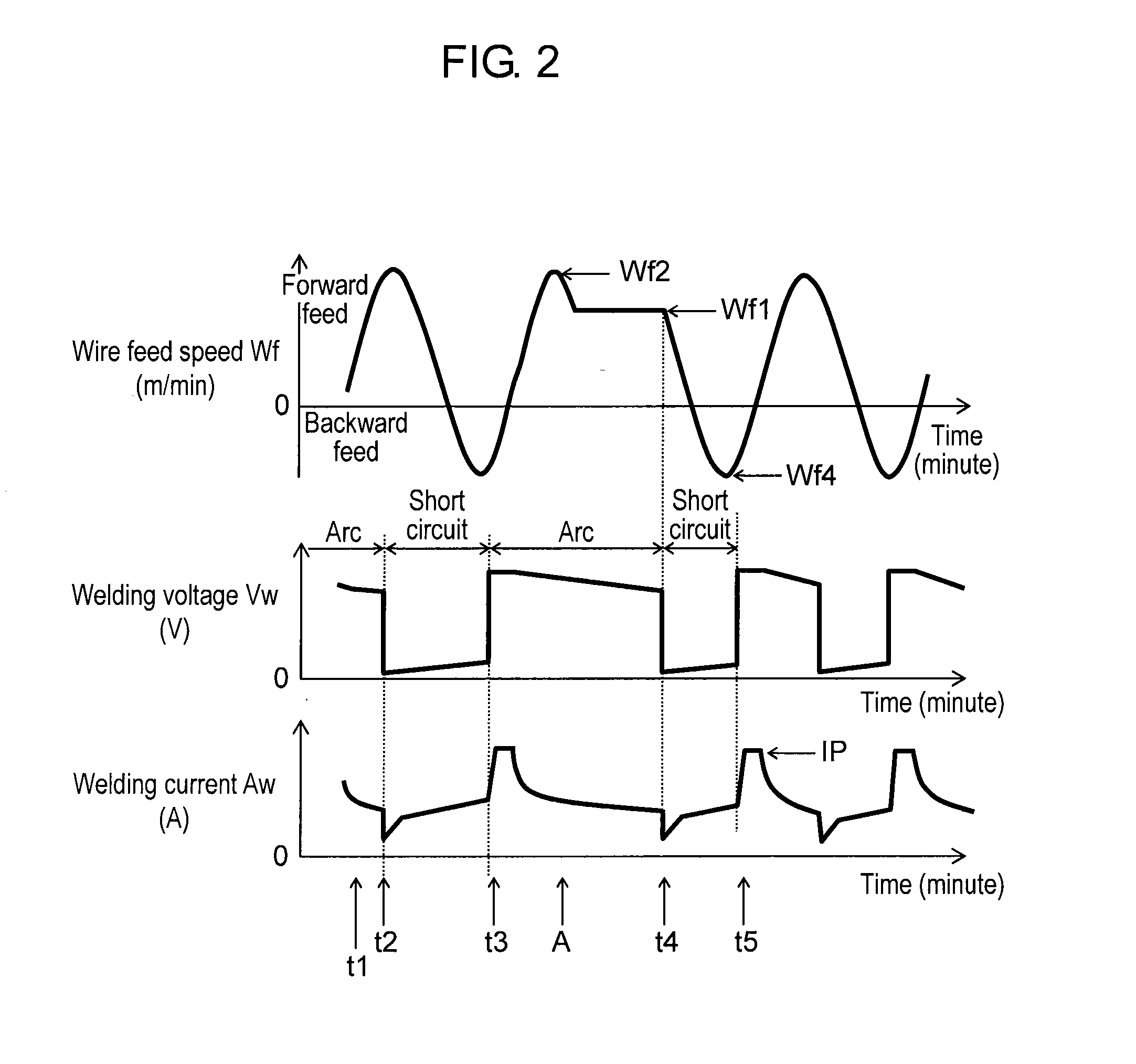
[0027]FIG. 1 is a schematic diagram of an arc welding device in this exemplary embodiment. FIG. 2 shows waveforms of a wire feed speed, welding voltage, and welding current when welding takes place adopting a consumable electrode arc welding control method in this exemplary embodiment.

[0028]In FIG. 1, input AC voltage from input power supply 1 is applied to welding power supply 14, and is rectified by primary rectifying element 3. Switching element 4 switches and controls an output of primary rectifying element 3 to an output appropriate for welding, and main transformer 2 converts the input power supply to an output appropriate for welding. Secondary rectifying element 6 rectifies one of secondary outputs insulated from the primary side in main transformer 2, and reactor 5 smoothes it to a current appropriate for welding. The current smoothed by reactor 5 is applied to torch 18 via one welding power output terminal 14a. The other secondary output of main transformer 2 is connected ...

second exemplary embodiment

[0048]Parts that are same as the first exemplary embodiment are given the same reference marks to omit duplicate detailed description in this exemplary embodiment. Major difference from the first exemplary embodiment is the control of wire feed speed Wf when arc is not generated during backward wire feed in the short circuit period between generation of short circuit and generation of arc.

[0049]FIG. 1 used in the first exemplary embodiment shows a schematic diagram of a consumable electrode arc welding device also applicable to this exemplary embodiment. FIG. 3 shows waveforms of a wire feed speed, welding voltage, and welding current when welding takes place adopting a consumable electrode arc welding control method in this exemplary embodiment.

[0050]Time t1 in FIG. 3 is within the arc period where arc is generated. Outputs of welding voltage Vw and welding current Aw are controlled to form an appropriate droplet in order to smoothly transfer the droplet at a wire end in a coming s...

third exemplary embodiment

[0063]Parts that are same as the first and second exemplary embodiments are given the same reference marks to omit duplicate detailed description. Major difference from the first and second exemplary embodiments is the control of wire feed speed to achieve a predetermined average wire feed speed for each set welding current by calculating an average wire feed speed for every cycle of cyclic wire feed speed.

[0064]FIG. 1 used in the first and second exemplary embodiments show a structure also applicable to a consumable electrode arc welding device in this exemplary embodiment. FIG. 4 shows waveforms of a wire feed speed and average feed speed when welding takes place adopting the consumable electrode arc welding control method in this exemplary embodiment.

[0065]A dotted line of Wfs1 in FIG. 4 shows a reference average feed speed that is set for each set welding current. As described later, this is set based on set current. Reference average feed speed Wfs1 is preset to that equivalent...


PUM

PropertyMeasurementUnit
currentaaaaaaaaaa
speedaaaaaaaaaa
feed speedaaaaaaaaaa

Abstract

If a short circuit does not occur during deceleration of a wire feed speed in forward feed of a welding wire before the wire feed speed reaches a predetermined wire feed speed, a cyclic change is stopped and the wire feed speed is constantly controlled at the first feed speed. If a short circuit occurs during forward feed at the first feed speed, deceleration from the first feed speed starts, and the cyclic change is resumed for welding. This achieves uniform weld bead without increasing spatters even if any external disturbance such as change of distance between a tip and base material occurs.

Description

TECHNICAL FIELD[0001]The present invention relates to consumable electrode arc welding methods and consumable electrode arc welding devices that feed a welding wire, which is a consumable electrode, and welds the wire onto a workpiece to be welded by alternately generating a short circuit state and an arc condition between the consumable electrode and the workpiece.BACKGROUND ART[0002]Demand for faster welding speed and less spatter, so as to increase productivity, have been increasing in the welding industry. Faster welding speed increases production quantity per time, and thus welding productivity increases. Less spattering reduces a post-treatment process of removing spatter attached to a base material, and thus welding productivity also increases.[0003]FIG. 5 shows waveforms of wire feed speed Wf, welding voltage Vw, and welding current Aw in conventional arc welding. First, conventional arc welding is described with reference to FIG. 5. In a known welding process, the wire feed...

Claims


Application Information

Patent Timeline
Patent Type & Authority Applications(United States)
IPC IPC(8): B23K9/24B23K9/095B23K9/00
CPCB23K9/0731B23K9/09B23K9/0735B23K9/125B23K9/124
Inventor KAWAMOTO, ATSUHIROMUKAI, YASUSHIFUJIWARA, JUNJIMISHIMA, TOSHIYUKIKOWA, MASARU
Owner PANASONIC CORP
Why Eureka
Try Eureka