Turbine blade tip with vortex generators

a turbine blade and generator technology, applied in the field of turbine blade tips, can solve problems such as insufficient distance, and achieve the effect of reducing tip leakag

Inactive Publication Date: 2012-03-29
SIEMENS ENERGY INC
View PDF15 Cites 20 Cited by
  • Summary
  • Abstract
  • Description
  • Claims
  • Application Information

AI Technical Summary

Benefits of technology

[0009]During turbine engine operation, the turbine blades are attached to a rotor assembly that rotates as hot gases flow past the blades from the combustor. The rib and the vortex generators reduce the leakage of the hot gases past the tip of the blades. In particular, the vortex generators create vortices. The vortices assist in reducing the hot gas leakage at the tip.
[0010]An advantage of this invention is that the vortex generators form geometric blockages that reduce leakage in addition to the rib forming the squealer tip.
[0011]Another advantage of this invention is that the vortex generators create additional turbulence at the tip in the tip flow, thereby creating additional resistance to air flow passing over the tip.

Problems solved by technology

The vortex generators may extend radially outward from the tip wall but not a distance sufficient to contact a stationary outer wall during turbine engine operation.

Method used


Image

  • Turbine blade tip with vortex generators
  • Turbine blade tip with vortex generators
  • Turbine blade tip with vortex generators

Examples


Embodiment Construction

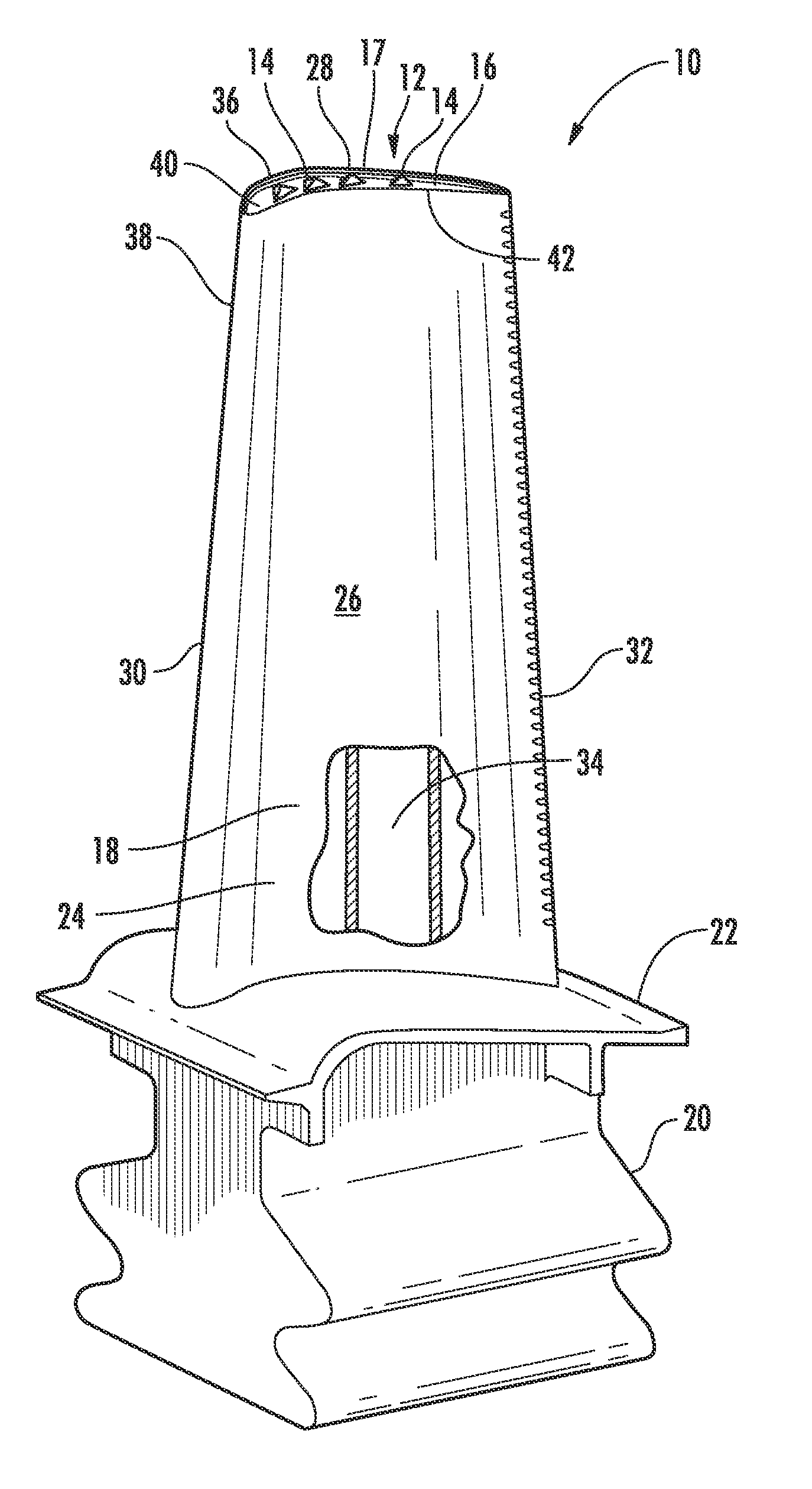
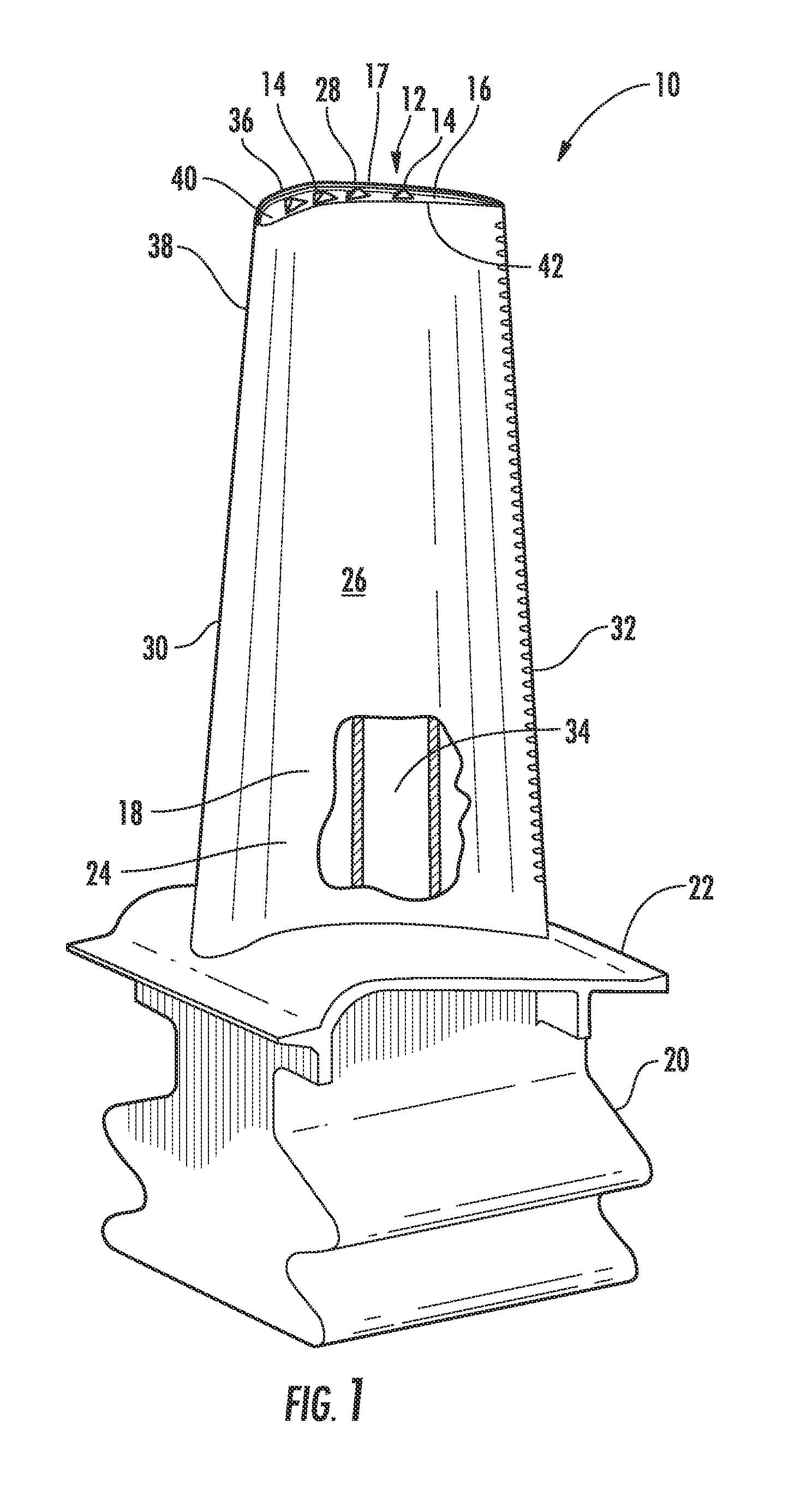
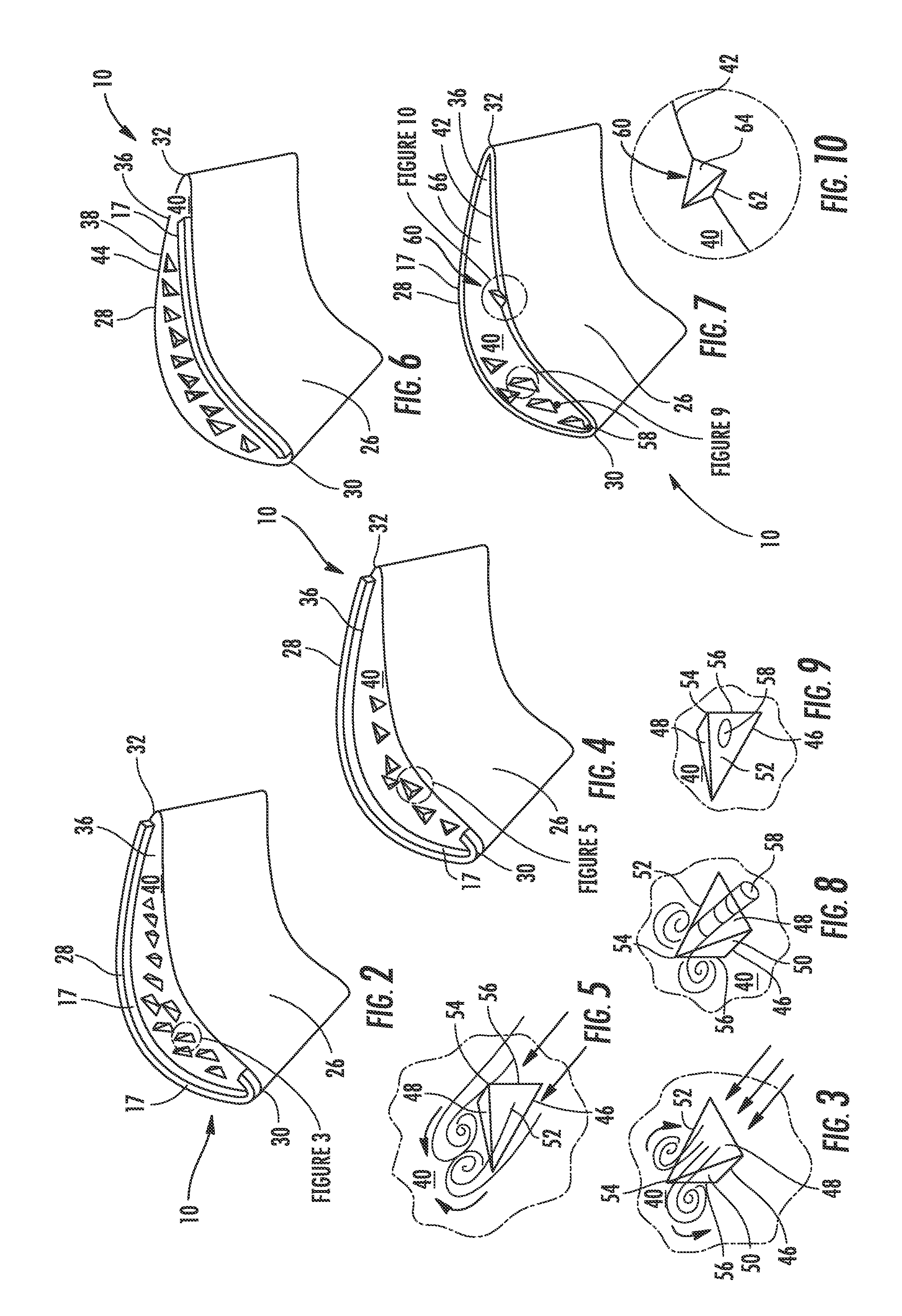
[0024]As shown in FIGS. 1-10, this invention is directed to a turbine blade tip leakage prevention system 10 for turbine blades 12 used in turbine engines to reduce tip leakage during operation of the turbine engines. In particular, the blade tip leakage prevention system 10 may include one or more vortex generators 14 on a tip wall 16 of the turbine blade 12. The vortex generators 14 may extend radially outward from the tip wall 16 but not a distance sufficient to contact a stationary outer wall during turbine engine operation. In at least one embodiment, the vortex generators 14 may extend a distance from the tip wall 16 generally equal to a rib 17 forming a squealer tip. The vortex generators 14 may be positioned in a number of different positions to limit leakage of gas path gases between the tip of the turbine blade 12 and a stationary outer wall.

[0025]The turbine blade 12 may be formed from a generally elongated blade 18 coupled to the root 20 at the platform 22. Blade 18 may ...


PUM


Abstract

A turbine blade for a turbine engine having a tip with one or more vortex generators for reducing tip leakage during operation of the turbine engine. The vortex generators may extend radially outward from the radially outer surface of the tip wall. The vortex generator may be positioned between a rib extending radially outward from the radially outer surface of the tip wall and an intersection between the outer surface of the tip wall and an outer surface on the pressure side. The vortex generators may include a base and three sides forming a triangular point with a first side having a larger surface are than second and third sides. One or more film cooling holes may be formed in the tip wall to provide cooling air to the tip. In one embodiment, film cooling holes may be positioned in one or more vortex generators.

Description

FIELD OF THE INVENTION[0001]This invention is directed generally to turbine blades for gas turbine engines, and more particularly to turbine blade tips.BACKGROUND[0002]Typically, gas turbine engines include a compressor for compressing air, a combustor for mixing the compressed air with fuel and igniting the mixture, and a turbine blade assembly for producing power. Combustors often operate at high temperatures that may exceed 2,500 degrees Fahrenheit. Typical turbine combustor configurations expose turbine blade assemblies to these high temperatures. As a result, turbine blades must be made of materials capable of withstanding such high temperatures. In addition, turbine blades often contain cooling systems for prolonging the life of the blades and reducing the likelihood of failure as a result of excessive temperatures.[0003]The hot combustion gases flow from the combustor and past the blades of the rotor assembly. The combustion gases cause the rotor assembly to rotate. Some of t...

Claims


Application Information

Patent Timeline
Patent Type & Authority Applications(United States)
IPC IPC(8): F01D5/08
CPCF01D5/187F01D5/20F05D2260/2212F05D2240/127F05D2250/21F05D2210/33
Inventor BEECK, ALEXANDER R.BROWN, GLENN E.
Owner SIEMENS ENERGY INC
Why Eureka
Try Eureka