Radio frequency power amplifier

a power amplifier and radio frequency technology, applied in the field of radio frequency modules, can solve the problems of deteriorating transmission quality, reducing signal level, and affecting the performance of the amplifier, so as to reduce the effect of exogenous noise, reduce the effect of unnecessary signals, and reduce the effect of directional couplers

Inactive Publication Date: 2012-03-29
PANASONIC CORP
View PDF11 Cites 4 Cited by
  • Summary
  • Abstract
  • Description
  • Claims
  • Application Information

AI Technical Summary

Benefits of technology

[0011]Furthermore, when the isolator is omitted, a reflective wave from the end of the antenna bounces back to the directional coupler. This causes a significant effect in detecting the transmission power. In order for accurate detection of the transmission power, the direction of the directional coupler is an important factor.
[0012]Patent Literature 1 discloses an example of a radio frequency module having a radio frequency power amplifier and a directional coupler both included in a single multi-layer board. In this example, the upper-layer portion of the radio frequency module has the radio frequency power amplifier and the lower-layer portion of the radio frequency module has the directional coupler. A main line and a sub line forming the directional coupler are vertically arranged with each having a different line width. Accordingly, Patent Literature 1 shows how the directional coupler improves its coupling accuracy. Patent Literature 1, however, fails to disclose the isolation between the radio frequency power amplifier and the directional coupler, and a counter measure against interference of outside noise with the directional coupler. In addition, the radio frequency module in Patent Literature 1 is difficult to be manufactured in a low profile since (i) the radio frequency power amplifier and the directional coupler are respectively formed in the upper and the lower layers from the middle of the multi-layer board, and (ii) this structure requires many layers.
[0014]The present invention is conceived in view of the above problems and has an object to offer a radio frequency module having a radio frequency power amplifier and a directional coupler integrated and, in particular, a small and inexpensive radio frequency module in which the radio frequency power amplifier and the directional coupler can provide excellent characteristics, and a wireless device equipped with the radio frequency module.
[0017]Moreover, the thermal via also works as a ground via for the radio frequency power amplifier. Thus, the thermal via is provided between the bias line of the radio frequency power amplifier and the directional coupler. Accordingly, the bias line and the directional coupler are fully isolated with each other, eliminating the need for forming the bias line on a layer on which directional coupler is not formed.
[0018]The radio frequency module may further include a ground via which is provided (i) between the first ground layer and a second ground layer which is provided below the directional coupler, and (ii) between the directional coupler and an end of the multi-layer board. This structure contributes to reducing the effect of exogenous noise to the directional coupler. Furthermore, the ground via can improve the effect of the first ground layer as a ground, which contributes to improving the performance of the radio frequency power amplifier.
[0019]The present invention relates to a radio frequency module having a radio frequency power amplifier and a directional coupler integrated in a multi-layer board. More particularly, the present invention provides (i) a small, inexpensive, and high-performance radio frequency module having the radio frequency power amplifier, the main line and the sub line of the directional coupler, and a ground via which are optimally arranged, and (ii) a small and inexpensive wireless device equipped with the radio frequency module.FURTHER INFORMATION ABOUT TECHNICAL BACKGROUND TO THIS APPLICATION

Problems solved by technology

Unfortunately, integration of components in the radio frequency module causes problems such as signal interference and capacity deterioration.
CDMA and W-CDMA involve frequent control of transmission power since, using the systems, the interference with the power of another mobile terminal deteriorates the transmission quality.
Thus, in addition to the accuracy problem, the directional coupler in the radio frequency module is susceptible to interference with the signals from other integrated components.
Patent Literature 1, however, fails to disclose the isolation between the radio frequency power amplifier and the directional coupler, and a counter measure against interference of outside noise with the directional coupler.
In addition, the radio frequency module in Patent Literature 1 is difficult to be manufactured in a low profile since (i) the radio frequency power amplifier and the directional coupler are respectively formed in the upper and the lower layers from the middle of the multi-layer board, and (ii) this structure requires many layers.
However, this example fails to disclose the isolation between the radio frequency power amplifier and the directional coupler and the structure of the directional coupler.

Method used


Image

  • Radio frequency power amplifier
  • Radio frequency power amplifier
  • Radio frequency power amplifier

Examples


embodiment 1

[0026]Described hereinafter is a radio frequency module according to Embodiment 1 of the present invention with reference to the drawings.

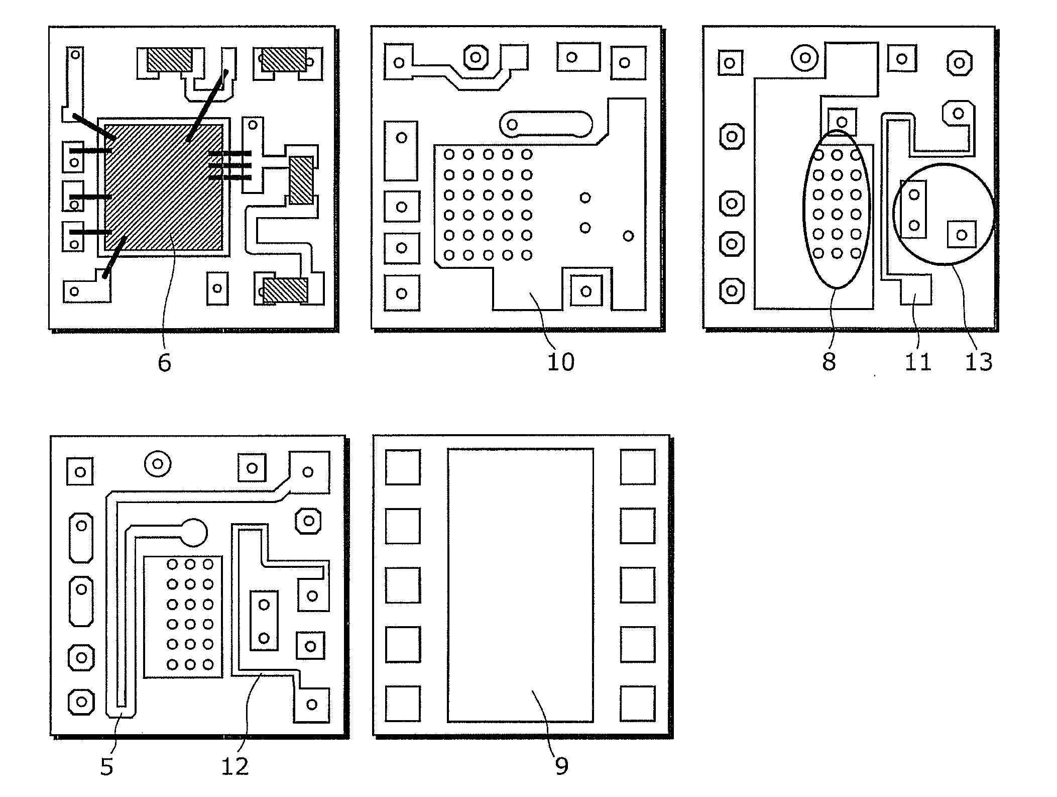
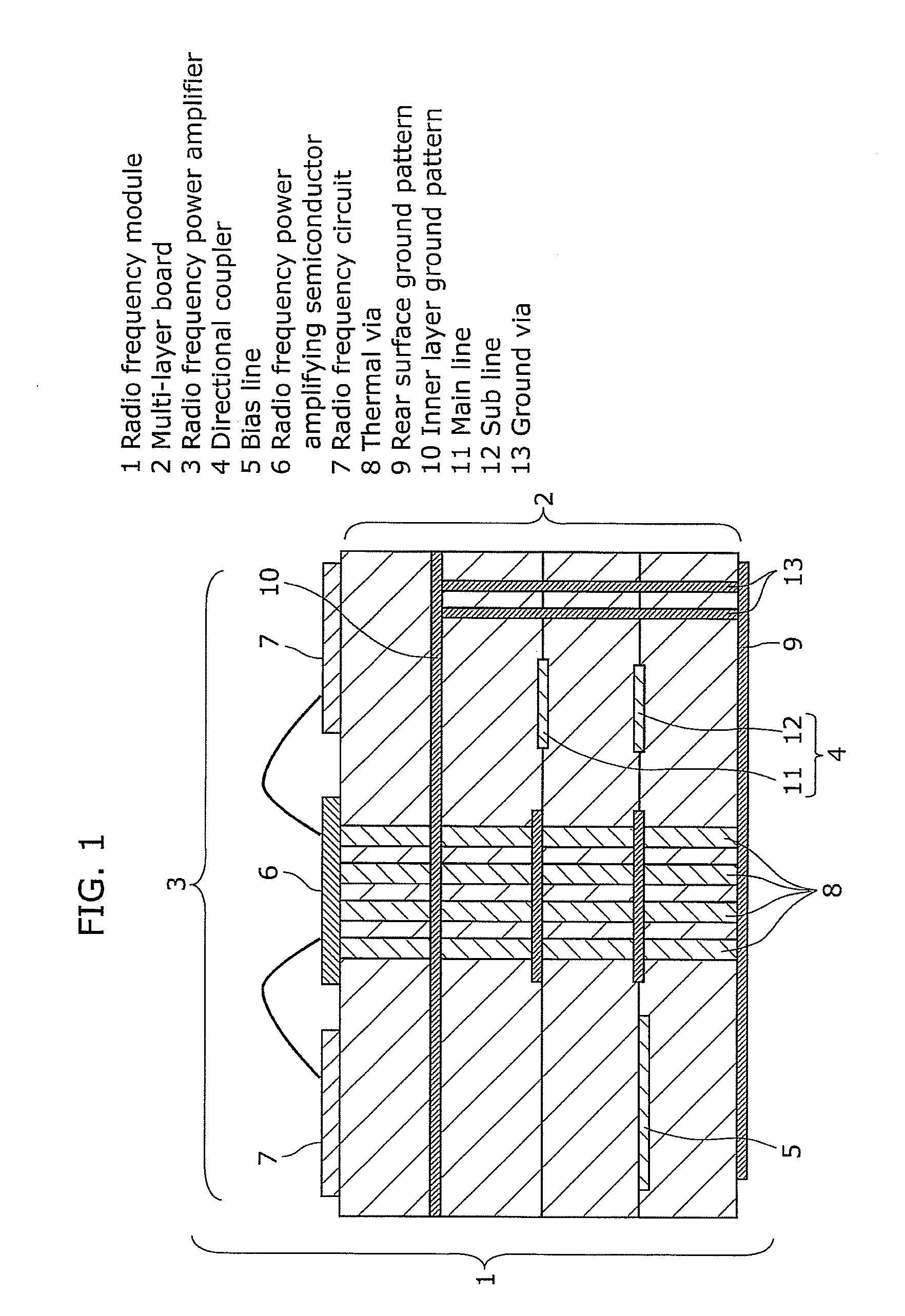
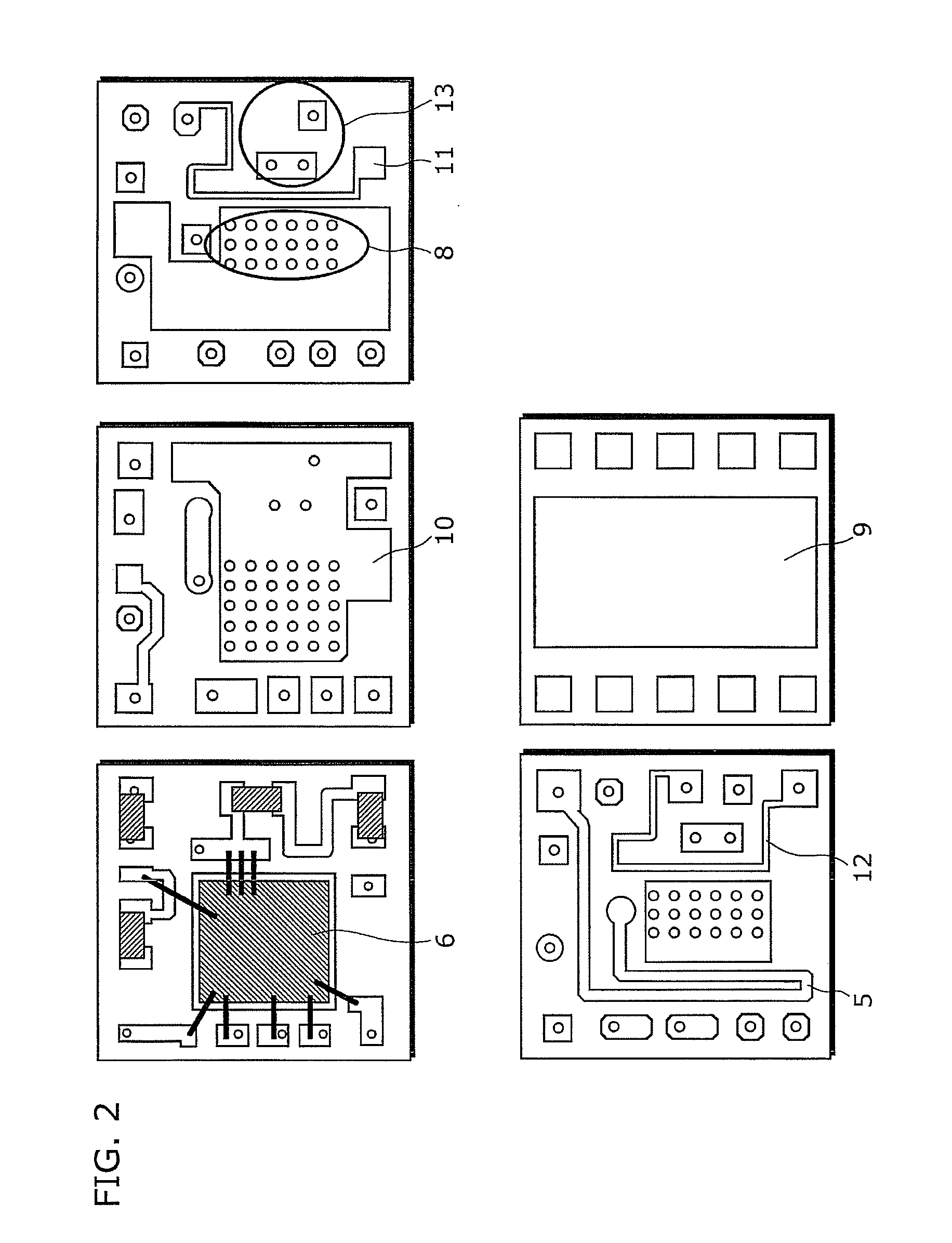
[0027]FIG. 1 depicts a cross-sectional view of a radio frequency module of the present invention. FIG. 2 depicts a development view of a multi-layer board in the radio frequency module.

[0028]A radio frequency module 1 in FIG. 1 includes a multi-layer board 2, a radio frequency power amplifier 3 provided on the top of the upper-most layer of the multi-layer board 2, a directional coupler 4, and a line 5. The directional coupler 4 monitors a signal provided from the radio frequency power amplifier 3 formed in inner layers of the multi-layer board 2. The line 5 supplies a bias to the radio frequency power amplifier 3. Examples of the multi-layer board 2 includes, but not limited to, multi-layer boards made of ceramic or resin. Any multi-layer board is usable as far as a wiring pattern is formed thereon. On the upper-most layer of the multi-layer boar...


PUM


Abstract

The present invention offers a radio frequency module having a radio frequency power amplifier and a directional coupler integrated in a multi-layer board, and in particular, a small, inexpensive, and high-performance radio frequency module, and a small and inexpensive wireless device equipped with the radio frequency module. The radio frequency module includes: a multi-layer board; a radio frequency power amplifier formed on top of the multi-layer board; a directional coupler having two layers vertically arranged in the multi-layer board; an internal ground pattern provided between the radio frequency power amplifier and the directional coupler; and thermal vias used for the radio frequency power amplifier and provided (i) between the internal ground pattern and a rear surface ground pattern and (ii) between the directional coupler and a bias line which is (i) provided in the same layer as the directional coupler and (ii) used for the radio frequency power amplifier.

Description

BACKGROUND OF THE INVENTION[0001](1) Field of the Invention[0002]The present invention relates to radio frequency modules used for devices transmitting and receiving radio frequency signals.[0003](2) Description of the Related Art[0004]In the field of recent mobile communications, complex mobile-phone terminals, having two or more communication modes and frequency bands integrated, are going the mainstream of mobile communications terminals. Since such a complex mobile communications terminal employs various communication modes and frequencies to be used as carrier waves, a radio frequency circuit block is required for each communication mode and frequency in order for the radio frequency circuit block to correspond to the communication mode and the frequency of each carrier wave. This causes the mobile communications terminal to be greater in size. In order to build smaller mobile communications terminals, there are important factors to take: (i) the reduction of the number of comp...

Claims


Application Information

Patent Timeline
Patent Type & Authority Applications(United States)
IPC IPC(8): H04B1/04H03F3/19H04B1/40H05K3/46
CPCH01L2224/48091H01L2224/48227H01L2224/49171H01L2224/49175H05K1/0243H01L2924/19105H05K1/0298H04B1/036H05K1/0206H01L2924/00014H01L2924/00H01L2924/3011
Inventor OHASHI, KAZUHIKOENOMOTO, SHINGO
Owner PANASONIC CORP
Why Eureka
Try Eureka