
Robot calibration apparatus and method for same

a robot and calibration method technology, applied in the direction of electrical programme control, program control, instruments, etc., can solve the problems of difficult to build a perfect robot without, defect in the completed product, and considerable time required to amend the defect, so as to facilitate the calibration and be easily applicable to the production line

Inactive Publication Date: 2012-03-29
EZROBOTICS
View PDF3 Cites 20 Cited by
  • Summary
  • Abstract
  • Description
  • Claims
  • Application Information

AI Technical Summary

Benefits of technology

[0010]The invention proposes a robot calibration apparatus and a robot calibration method, which easily perform calibration and are easily applicable to a production line by selecting and measuring a plurality of points from among not only a reference point of which position information is pre-known, but also arbitrary points on a reference line of which a linear equation is pre-known and arbitrary points on a reference plane of which a plane equation is pre-known relative to the reference coordinate system of the measurement jig, and performing calibration by using position information of the plurality of measured points. In other words, the invention provides a robot calibration apparatus and a robot calibration method, which use position information of a point measured at any position on a reference line or reference plane on a measurement jig.

Problems solved by technology

Here, each robot performs such an operation by inputting a design value to a computer, but it is difficult to build a perfect robot without an error in each design value due to driving errors in various driving devices enabling the robot to operate, a manufacturing error of the robot, and an installation error of a tool.
Such an error may be small but is propagated and eventually becomes a big error while actually defining a process, thereby causing a defect in a completed product.
Thus a considerable time is required to amend the defect.
However, according to a conventional calibration method, only the points set on the measurement jig and of which the position information is known, for example, a center position of a circle, are measured, and thus the measurement postures of the robot are very limited during measuring, and sometimes, measurement may not be possible.

Method used


Image

  • Robot calibration apparatus and method for same
  • Robot calibration apparatus and method for same
  • Robot calibration apparatus and method for same

Examples


Embodiment Construction

[0017]Hereinafter, the present invention will be described more fully with reference to the accompanying drawings, in which exemplary embodiments of the invention are shown.

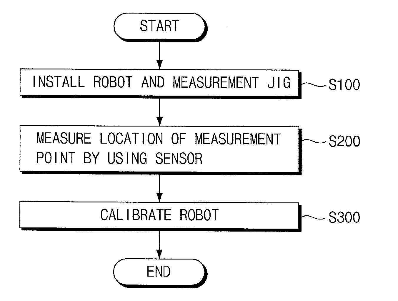
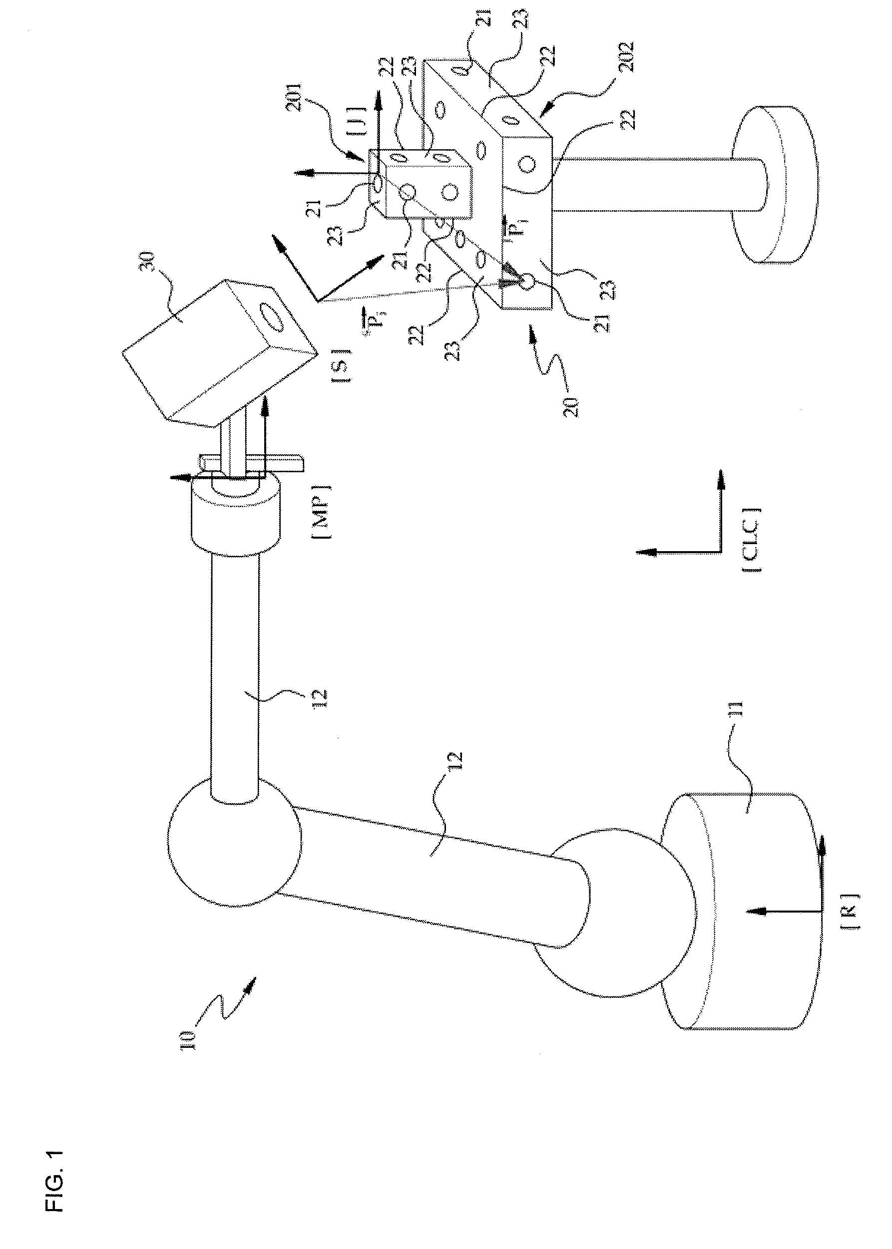
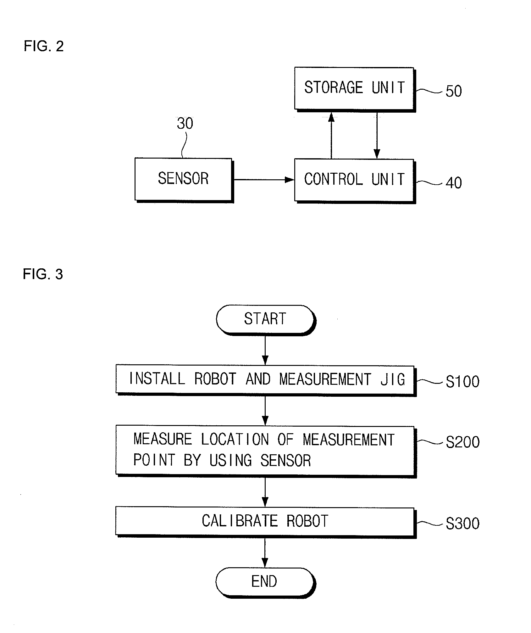
[0018]FIG. 1 is a schematic diagram of a robot calibration apparatus according to an embodiment of the present invention, and FIG. 2 is a block diagram for describing operations of the robot calibration apparatus of FIG. 1.

[0019]Referring to FIGS. 1 and 2, the robot calibration apparatus according to the current embodiment is used to precisely predict various parameters controlling kinematic equations, such as a position and orientation of a base 11 of a robot 10, a parameter controlling a robot kinematic equation, and a position and orientation of installing a tool (not shown). When parameters precisely predicted are used while controlling the robot 10 to move to an arbitrary position, a position and orientation of a tool reference coordinate system or a position of a tool center point viewed from a user coordin...


PUM


Abstract

A robot calibration apparatus and a robot calibration method. The robot calibration apparatus includes:a measurement jig including a plurality of reference points of which positions are pre-known, one or more reference lines of which linear equations are pre-known, and one or more reference planes of which plane equations are pre-known relative to a reference coordinate system of the measurement jig, wherein arbitrary points from among the plurality of reference points, the plurality of arbitrary points on the one or more reference line, and the plurality of arbitrary points on the one or more reference plane are set as measurement points;a sensor coupled to a robot and measuring positions of a plurality of measurement points selected from among the measurement points on the measurement jig;and a control unit controlling the calibrated robot after calibrating the robot based on a plurality of pieces of calibration data including position information of the plurality of measurement points measured by the sensor, wherein at least one measurement point from among the plurality of measurement points is arranged on the reference line or the reference plane. Accordingly, the robot can be calibrated by using information of measuring an arbitrary position on the reference line or reference plane on the measurement jig, and thus limitation to the measurement posture of the robot can be remarkably reduced while measuring the positions of the measurement points, the position information of the measurement point can be easily obtained, and the robot calibration apparatus can be easily applied to a production line.

Description

BACKGROUND OF THE INVENTION[0001]1. Field of the Invention[0002]The present invention relates to a robot calibration apparatus and a robot calibration method, and more particularly, to a robot calibration apparatus and a robot calibration method, which calibrate a robot used to perform various accurate operations, such as welding, grinding, cutting, measuring, etc., instead of a person.[0003]2. Description of the Related Art[0004]Robots are widely used in the industrial fields in general, instead of people (to replace human beings or workmen). For example, robots coupled to tools are disposed on a production line to perform various operations to manufacture cars. As such, when the production line is built by coupling various tools to robots, cars may be manufactured in large quantities at a low price. Also, since a robot moves along a designed moving path to perform various operations, the quality (accuracy) of the operations may maintain the same level unlike when the operations ar...

Claims


Application Information

Patent Timeline
Patent Type & Authority Applications(United States)
IPC IPC(8): B25J13/08
CPCG05B2219/39045B25J9/1692Y02P80/40
Inventor BORM, JIN HWANKIM, JUNG MINPARK, SANG WOOK
Owner EZROBOTICS
Learn More