

Patient lifter with intraoperative controlled temperature air delivery system
- Summary
- Abstract
- Description
- Claims
- Application Information
AI Technical Summary
Benefits of technology
Problems solved by technology
Method used
Image

Examples
first embodiment
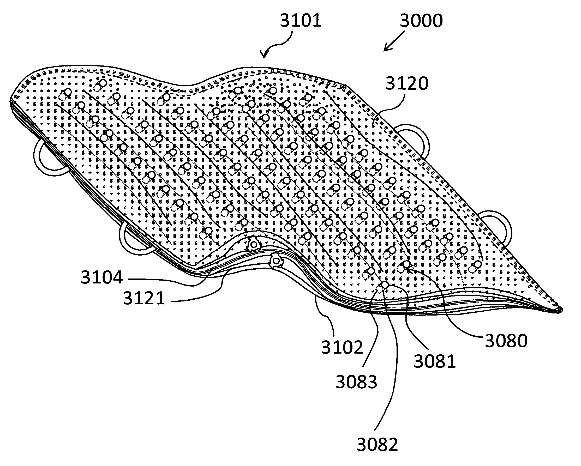
[0062]FIG. 2a illustrates at 2000 the subject invention. FIG. 2d illustrates a cross-section view taken along line V-V of FIG. 2a. Pad 2101 generally is a thin flexible matt construct provided with a top chamber 2120 and a bottom chamber 2121. Preferably, handles 2150 are provided at the foot and head region of the pad. Alternatively, the handles 2150 may also / or instead, be located on the sides of the pad. Pad 2101 includes a bottom surface 2102, a top surface 2103, and a separation barrier 2104 between and completely separating the top chamber 2120 and 2121. Barrier 2104 is preferably a diaphragm composed of a semi-flexible thin impervious material, such as a polymeric or silicone film or material. Top surface 2103 is provided with apertures 2105a and 2105b therein. Generally, apertures 2105a, located near the head portion of the pad 2101, may be larger than apertures 2105b located at the foot portion of pad 2101, and deliver an increased amount of comfort air to the upper portion...
second embodiment
[0088]In a second embodiment, the pad having a bottom chamber comprising two laterally separated inter-digitizing inflatable chambers therein, each being provided with an individually regulated compressed ambient air supply, for adjusting pressure points.
[0089]Advantageously, the Patient Lifter with Intraoperative Heater System provides:
[0090]i) a combination system with operative heater that delivers a warm or cold air stream surrounding a patient and a patient lifter / patient transport device;
[0091]ii) an intraoperative heater device that delivers heat from beneath a patient, and which can be used without a tent, the system having surgical drapes that are placed above the patient and function as a cover when heat is delivered from beneath the patient;
[0092]iii) an air-cushion forming mechanism for developing compressed ambient air pressure that is increased to a pre-selected high pressure, discharging air through said bottom surface of said bottom chamber to thereby create an air c...
PUM
 Abstract
Description
Claims
Application Information