
Manifolding Arrangement for a Modular Heat-Exchange Apparatus

a heat exchange apparatus and modular technology, applied in the field of heat exchangers, can solve the problems of the largest capital and operational costs of an otec installation, and achieve the effect of little or no pressure drop or backpressure developmen

Active Publication Date: 2012-04-05
LOCKHEED MARTIN CORP
View PDF13 Cites 22 Cited by
  • Summary
  • Abstract
  • Description
  • Claims
  • Application Information

AI Technical Summary

Benefits of technology

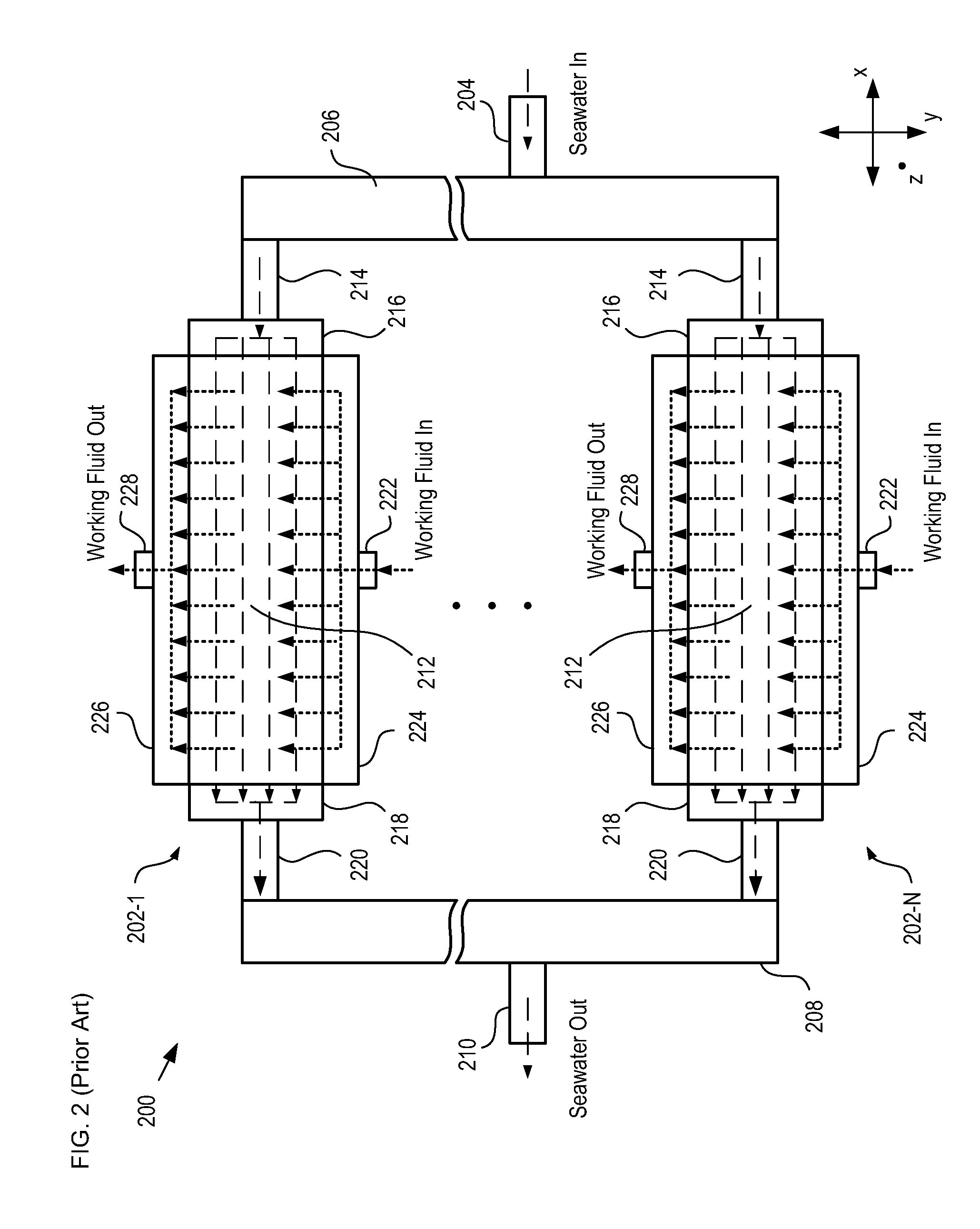
[0009]The first heat-exchanger module further comprises a second manifold having a third channel that receives the seawater after it has passed through the plurality of heat exchangers. The third channel provides the received seawater to a fourth channel that is characterized by a cross-section that increases monotonically from that of the third channel to a cross-section that matches a second port at a second pontoon. As a result, the fourth channel smoothly conveys the seawater to the second port with little or no pressure drop or development of backpressure.

Problems solved by technology

The heat exchangers and pumping systems that feed seawater to them represent some of the largest capital and operational costs of an OTEC installation.

Method used


Image

  • Manifolding Arrangement for a Modular Heat-Exchange Apparatus
  • Manifolding Arrangement for a Modular Heat-Exchange Apparatus
  • Manifolding Arrangement for a Modular Heat-Exchange Apparatus

Examples


Embodiment Construction

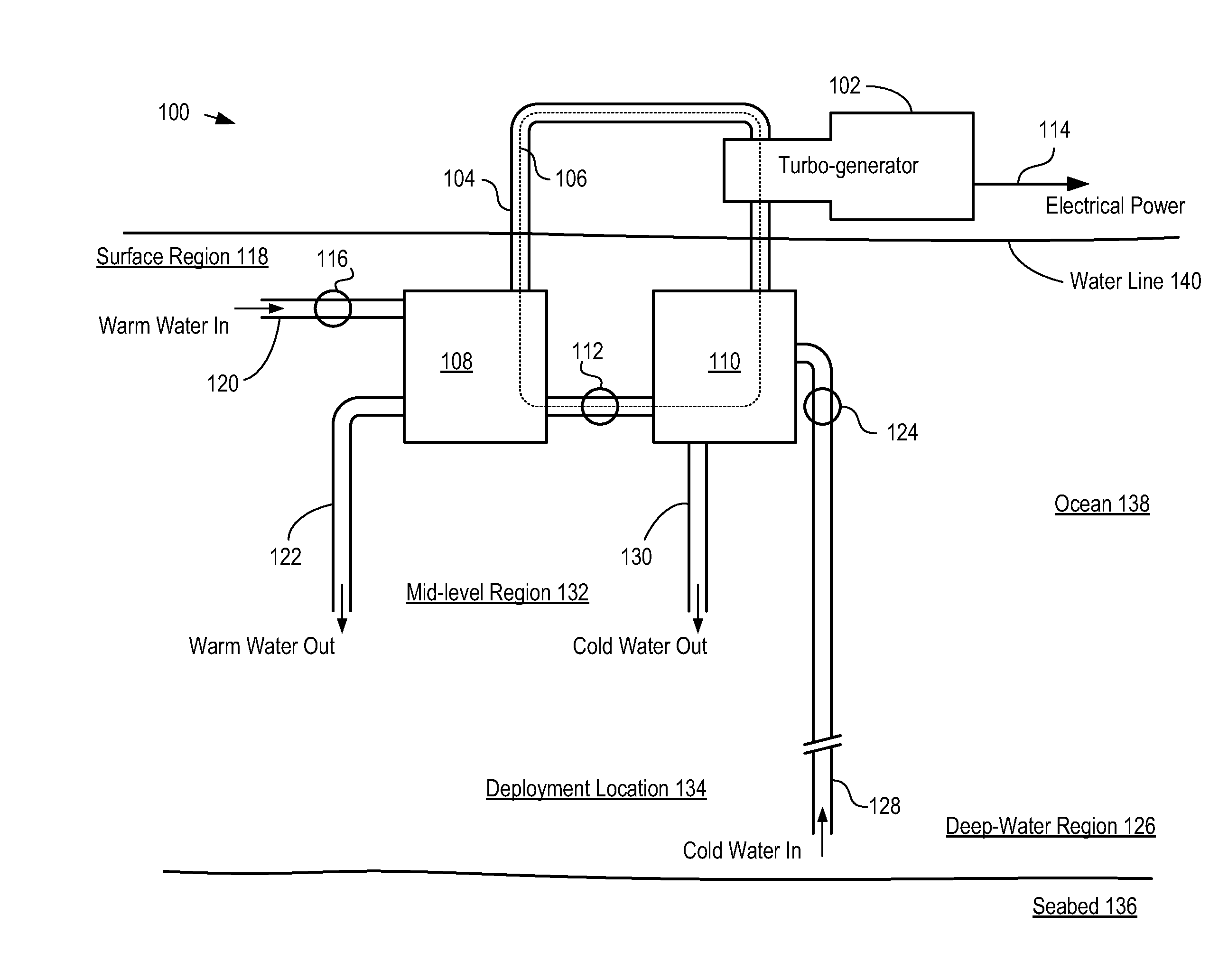
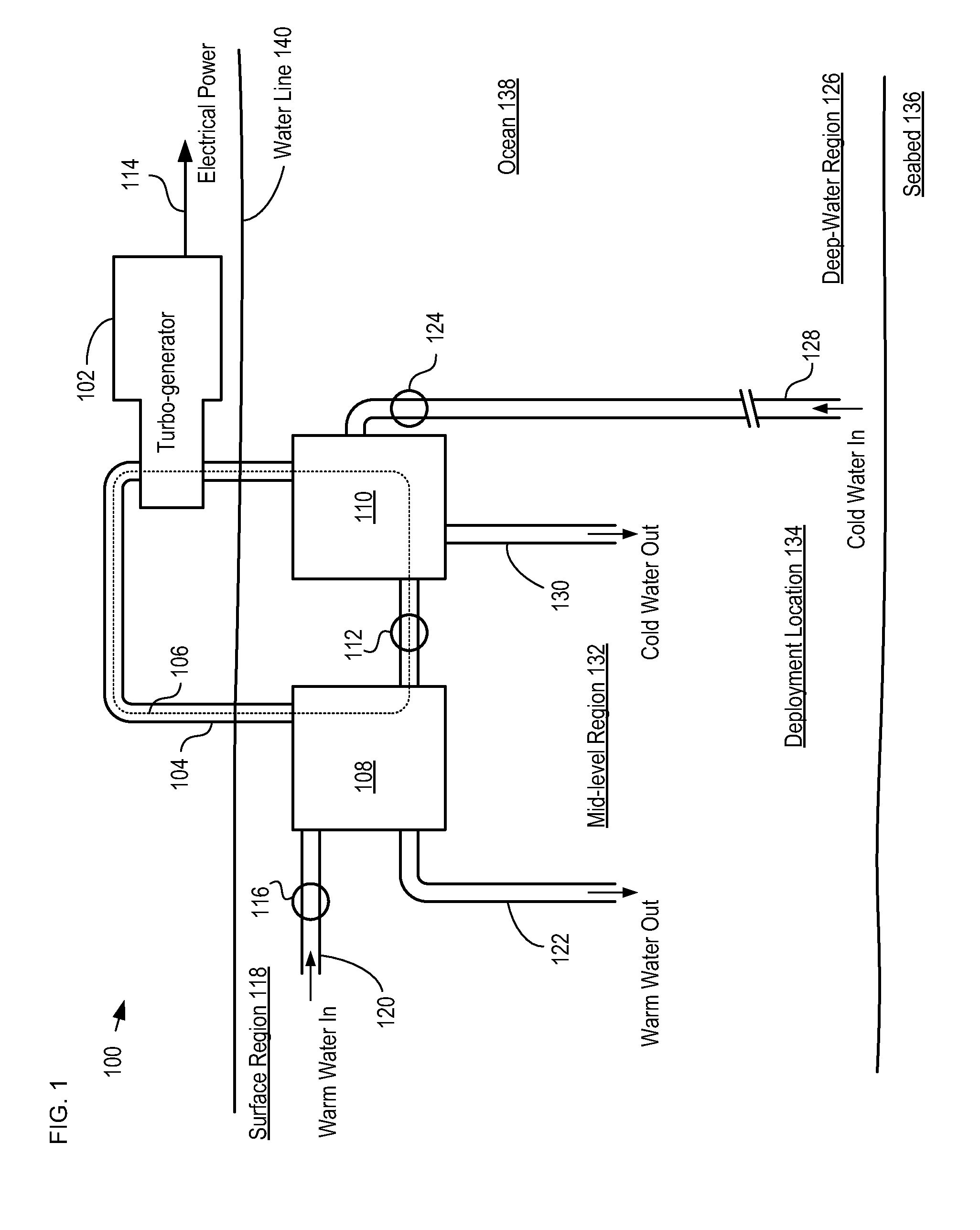
[0016]FIG. 1 depicts a schematic diagram of an OTEC power generation system in accordance with an illustrative embodiment of the present invention. OTEC system 100 comprises turbogenerator 102, closed-loop conduit 104, evaporator 108, and condenser 110.

[0017]OTEC system 100 is deployed in ocean 138 at deployment location 134. Deployment location 134 is typically an offshore location at which the ocean depth is greater than 1000 meters. In some embodiments, OTEC system 100 is deployed in a body of water other than an ocean (e.g., a lake, sea, etc.).

[0018]Collectively, turbogenerator 102, closed-loop conduit 104, evaporator 108, condenser 110, and pump 112 compose a Rankine-cycle heat engine that generates electrical energy based on the difference in the temperature of seawater in surface region 118 and the temperature of seawater in deep-water region 126.

[0019]Turbogenerator 102 is a conventional turbine-driven generator, typically mounted on an offshore platform. Turbogenerator 102 ...


PUM


Abstract

A heat-exchanger module that conveys a fluid through one or more heat exchangers with little or no pressure drop is presented. The heat-exchanger module comprises a first manifold that smoothly channels the fluid from a fluid source to each of the heat exchangers. The heat-exchanger module further comprises a second manifold that smoothly channels the fluid from the heat exchangers to a fluid sink. The manifolds are dimensioned and arranged to mitigate development of pressure drops in the fluid flow.

Description

CROSS REFERENCE TO RELATED APPLICATIONS[0001]This application claims the benefit of U.S. Provisional Patent Application Ser. No. 61 / 388,881, filed Oct. 1, 2010, entitled “Heat-exchange Apparatus with Pontoon-based Fluid Distribution System,” (Attorney Docket: 711-298us), which is incorporated herein by reference.FIELD OF THE INVENTION[0002]The present invention relates to heat exchangers in general, and, more particularly, to heat exchangers for ocean thermal energy conversion (OTEC) systems.BACKGROUND OF THE INVENTION[0003]An Ocean Thermal Energy Conversion (OTEC) system generates electrical energy based on a temperature difference between cold seawater deep in the ocean and warm seawater near the ocean surface. Typically, OTEC systems rely upon large, robust heat exchangers that transfer heat between a working fluid and the seawater as part of a Rankine-cycle engine.[0004]In the Rankine cycle, the working fluid is vaporized by absorption of heat from the warm seawater at one or mo...

Claims


Application Information

Patent Timeline
IPC IPC(8): F28F7/00
CPCY02E10/34F03G7/05Y02E10/30
Inventor LEVINGS, NATALIE B.JANSEN, EUGENE C.GILBERT, JARED D.NAGURNY, NICHOLAS J.
Owner LOCKHEED MARTIN CORP
Learn More