High Voltage Energy Harvesting and Conversion Renewable Energy Utility Size Electric Power Systems and Visual Monitoring and Control Systems for Said Systems

Active Publication Date: 2012-04-05
ALENCON ACQUISITION
View PDF4 Cites 49 Cited by
  • Summary
  • Abstract
  • Description
  • Claims
  • Application Information

AI Technical Summary

Benefits of technology

[0010]In one aspect the present invention is a renewable energy, utility size electric power system. The system has a high voltage, renewable energy harvesting network and a centralized grid synchronized multiphase regulated current source inverter system. The high voltage, renewable energy harvesting network has multiple strings of renewable energy collectors, with each of the strings having a DC output, and multiple renewable energy power optimizers distributed throughout the harvesting network. Each renewable energy power optimizer has at least one energy collector string power optimizer input connected to the DC output of at least one of the multiple strings of renewable energy collectors. Each of the multiple renewable energy power optimizers and transmitters has a high voltage DC output connected to a DC link. The centralized grid synchronized multiphase regulated current source inverter system is connected to the DC link and has a plurality of grid inverter package modules that can be connected to a high voltage electrical grid.

Problems solved by technology

For either a solar or wind renewable energy, utility size power system, the power system components are spread out over significantly more land than a conventional residential or commercial size power plant thus making physical visualization and control of the power system a challenge beyond that of the typical one line centralized control boards used for conventional size power plants.

Method used


Image

  • High Voltage Energy Harvesting and Conversion Renewable Energy Utility Size Electric Power Systems and Visual Monitoring and Control Systems for Said Systems
  • High Voltage Energy Harvesting and Conversion Renewable Energy Utility Size Electric Power Systems and Visual Monitoring and Control Systems for Said Systems
  • High Voltage Energy Harvesting and Conversion Renewable Energy Utility Size Electric Power Systems and Visual Monitoring and Control Systems for Said Systems

Examples


Embodiment Construction

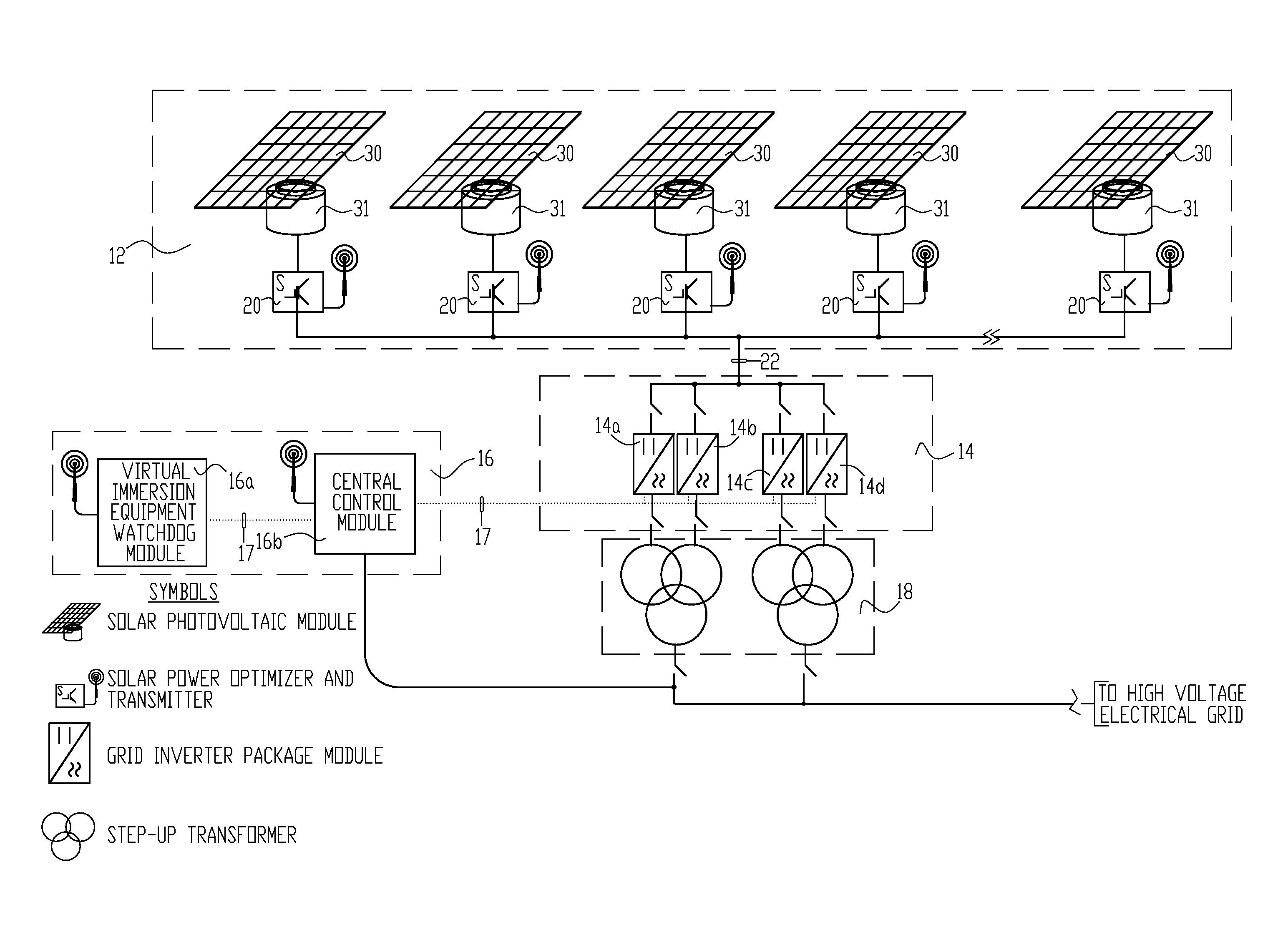
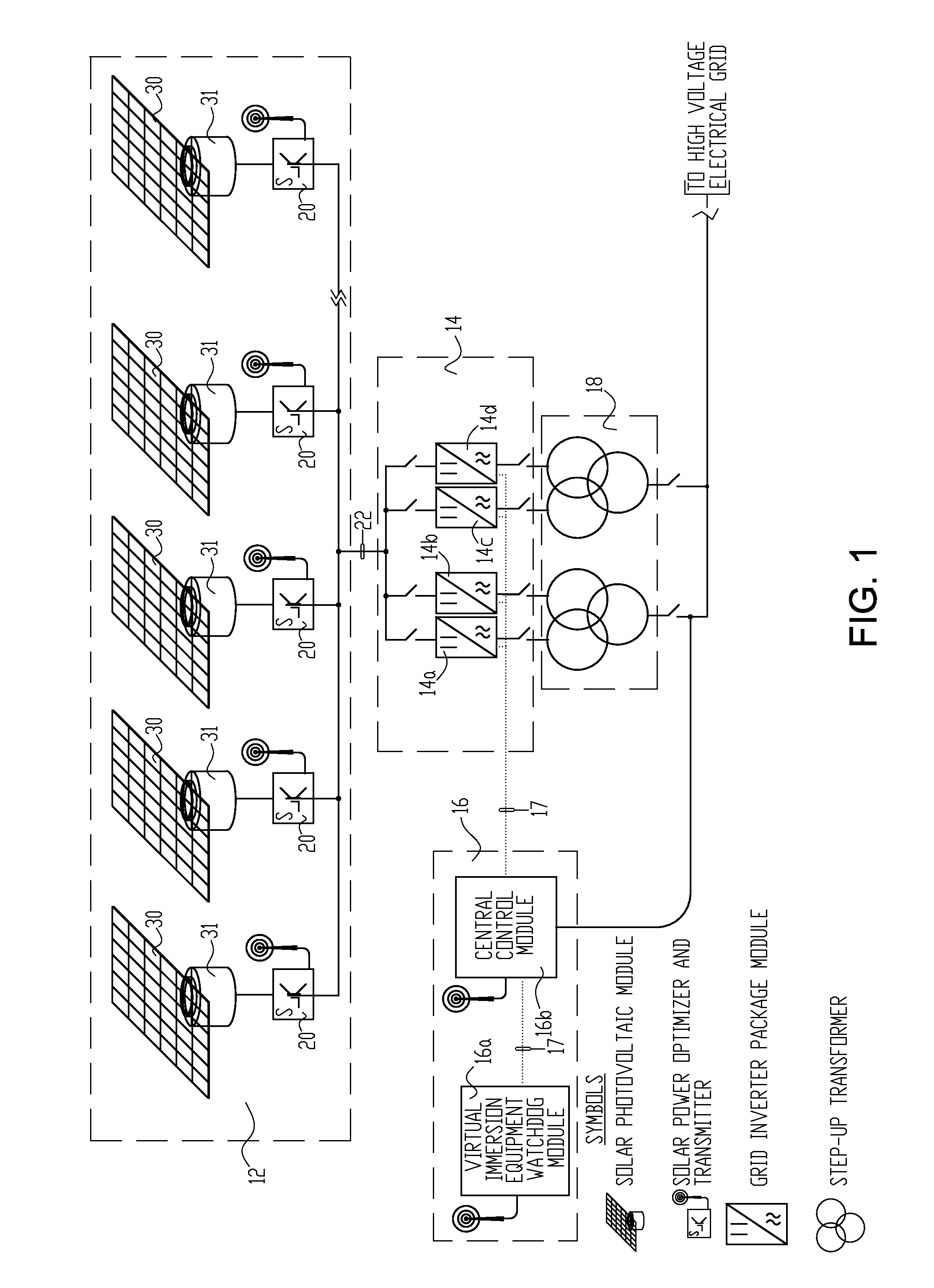
[0023]FIG. 1 is a simplified one-line block diagram of one example of a renewable energy, utility-size electric power system for the collection and conversion of solar energy, and a monitoring and control system of the present invention for the power system. In this example, there is a high voltage, solar photovoltaic energy collection (also referred to as “harvesting”) network 12; a centralized grid synchronized multiphase regulated current source inverter system 14; and an optional virtual immersion monitoring and control system 16. Step-up transformer 18 electrically isolates the outputs of the inverters in the grid inverter package (GrIP) modules 14a-14d from the high voltage electrical grid.

[0024]The optional high voltage, solar photovoltaic energy harvesting network and the centralized grid synchronized multiphase regulated current source inverter system are further described in U.S. patent application Ser. No. 12 / 542,891 (published as Publication No. 2009 / 0302686), which appl...


PUM


Abstract

A renewable energy, utility size electric power system is provided with a high voltage, renewable energy harvesting network connected by a direct current link to a centralized grid synchronized multiphase regulated current source inverter system. The harvesting network includes distributed renewable energy power optimizers and transmitters that control delivery of renewable energy to the grid synchronized multiphase regulated current source inverter system. A visual immersion monitoring and control system can be provided for a three-dimensional, visually-oriented, virtual reality display, command and control environment.

Description

CROSS REFERENCE TO RELATED APPLICATIONS[0001]This application claims the benefit of U.S. Provisional Application No. 61 / 389,816, filed Oct. 5, 2010, and U.S. Provisional Application No. 61 / 485,384, filed May 12, 2011, each of which is hereby incorporated by reference in its entirety.FIELD OF THE INVENTION[0002]The present invention relates generally to renewable energy, utility size electric power systems and, in particular, to high voltage energy harvesting and conversion renewable energy collection and conversion systems, and to visual monitoring and control systems for such systems.BACKGROUND OF THE INVENTION[0003]The term “renewable energy electric power systems” as used herein refers to utility size electric power systems that utilize a large number of interconnected photovoltaic modules to form a solar farm or power plant, or a large number of interconnected wind turbine generators that form a wind farm or power plant.[0004]Utility size (ranging from 5 to 100 megawatt (MWe) ou...

Claims


Application Information

Patent Timeline
Patent Type & Authority Applications(United States)
IPC IPC(8): H02J1/00
CPCH01L31/02021H02J3/383Y02E10/763H02J3/46Y02E10/563H02J3/386H02J2300/28H02J2300/24H02J3/381Y02E10/56Y02E10/76Y02E10/72H02J3/38H02J7/35F03D7/04
Inventor FISHMAN, OLEG S.SCHWABE, ULRICH K.W.
Owner ALENCON ACQUISITION
Why Eureka
Try Eureka