Eureka AIR delivers breakthrough ideas for toughest innovation challenges, trusted by R&D personnel around the world.

Transmission line probe for nmr

a transmission line and probe technology, applied in the field of nmr probes, can solve the problems of limiting the range of magnetic fields and/or nuclear species to which a conventional probe is sensitive without, and affecting the detection effect of conventional probes

Inactive Publication Date: 2012-04-05
MURPHREE JR DENNIS HAAGA +2
View PDF0 Cites 8 Cited by
  • Summary
  • Abstract
  • Description
  • Claims
  • Application Information

AI Technical Summary

Problems solved by technology

This limits the range of magnetic fields and / or nuclear species to which a conventional probe is sensitive without changing the frequency to which the resonant circuit is tuned.
In many applications of NMR this bandwidth limitation poses substantial difficulties.
It is particularly problematic in studies where it is desirable to vary the B0 field over a wide range of magnitudes, in studies of quadrupolar nuclei (which contain very broad resonances), in studies of multiple nuclear species, or whenever physical access to the tuning elements of the probe is limited.
It will be thus further apparent that the limitation in bandwidth is related to the presence of a resonant circuit.
This is often a time consuming process.
Because it is based on a resonant circuit, it suffers all of the bandwidth limitations inherent to conventional tuned probes.
In addition they are difficult to manufacture.
Furthermore, they are of geometries inappropriate for superconducting magnets with horizontal bores.
These probes are also not of the saddle coil geometry, and in addition suffer a frequency dependent impedance.
Furthermore, their electrical behavior is cyclic as a function of frequency rather than uniform.
However, these designs are still based on resonant circuits, thus suffer the penalties of limited bandwidth, stringent tuning, and frequency-dependent-impedance-matching requirements associated with resonant NMR probes.

Method used


Image

  • Transmission line probe for nmr
  • Transmission line probe for nmr
  • Transmission line probe for nmr

Examples


Embodiment Construction

[0029]Detailed descriptions of the preferred embodiment are provided herein. It is to be understood, however, that the present invention may be embodied in various forms. Therefore, specific details disclosed herein are not to be interpreted as limiting, but rather as a basis for the claims and as a representative basis for teaching one skilled in the art to employ the present invention in virtually any appropriately detailed system, structure or manner.

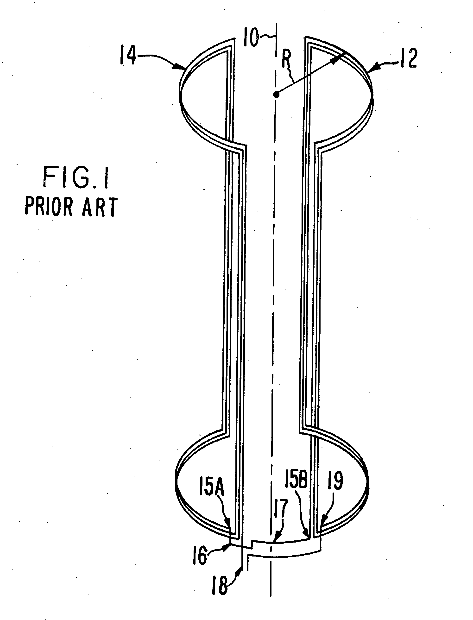
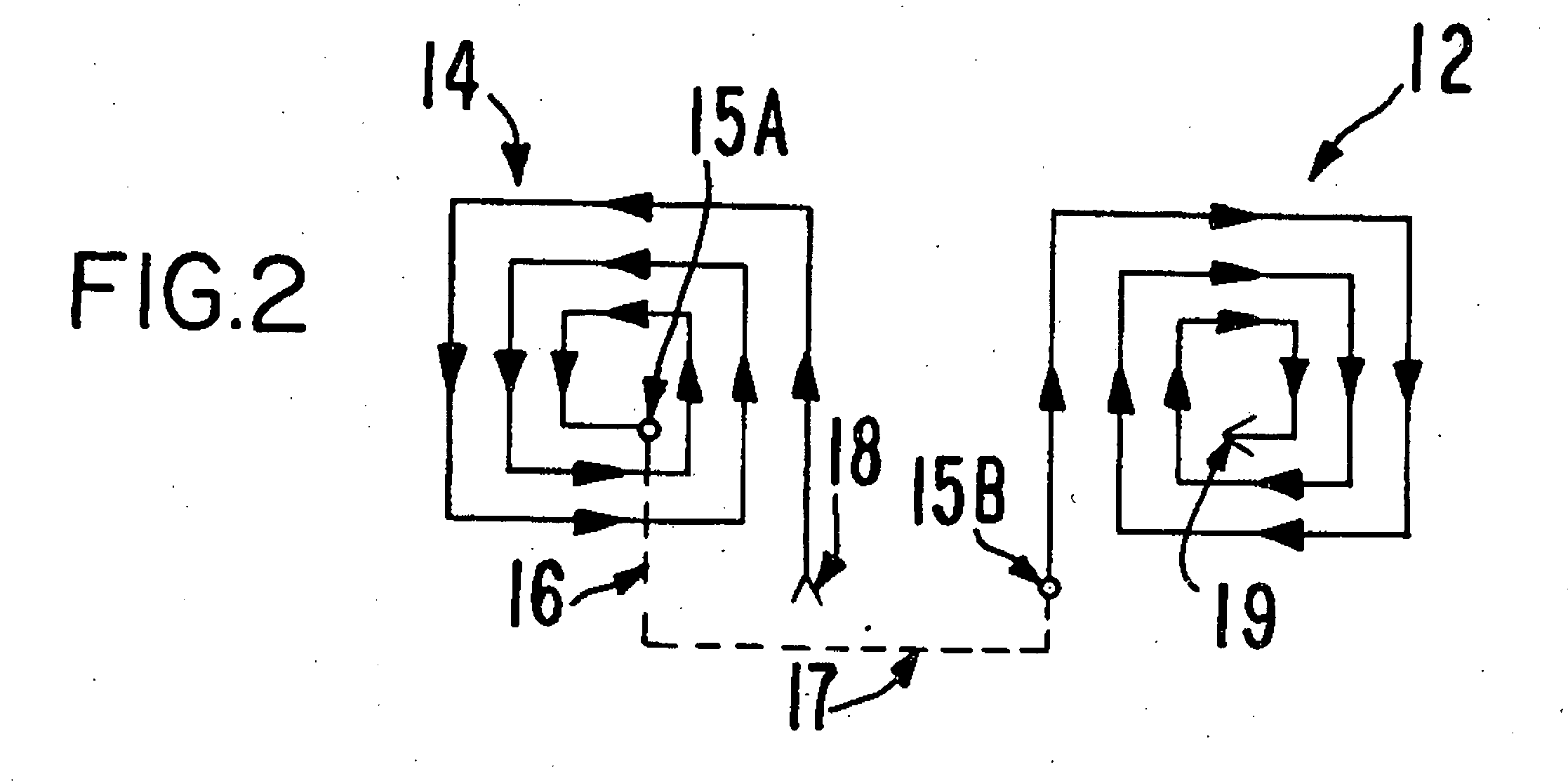
[0030]A prior art saddle coil of radius R is shown in FIG. 1. Two square spiral wound coil portions 12 and 14, of opposite helicities, are symmetrically arranged about an axis 10 to define a cylindrical volume there between. The inner terminal 15a of winding portion 14 must bridge at 16 windings of portion 14 to connect through connecting link 17 to the outer terminal 15b of portion 12. Terminals 18 and 19 are the external terminals of the series combination forming the complete saddle coil. For convenience, this prior art arrangemen...


PUM


Abstract

A probe for an NMR device is disclosed in which a saddle coil is disposed on one side of a flexible insulating material, and an additional conductor is disposed on the opposite side. The additional conductor and the conductors of the saddle coil create a capacitance across the insulating material. This capacitance acts with the inductance of the saddle coil such that the probe itself forms a transmission line. The probe is thus inherently broadband and requires no tuning. It also presents a constant impedance, thus facilitating impedance matching to an NMR spectrometer. In a preferred embodiment, a chip resistor is disposed on the flexible insulating material, terminating the transmission line.

Description

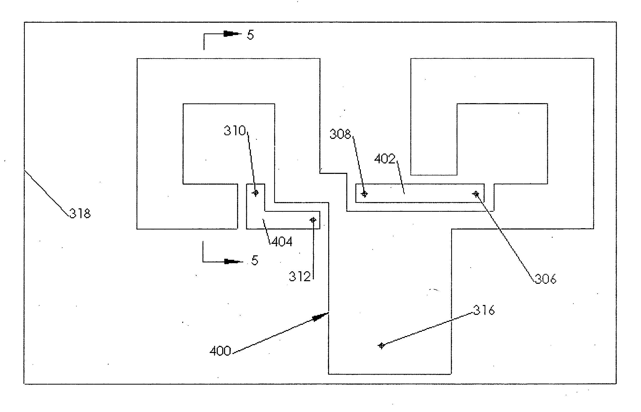
STATEMENT REGARDING FEDERALLY SPONSORED RESEARCH[0001]The U.S. Government has a paid-up license in this invention and the right in limited circumstances to require the patent owner to license others on reasonable terms as provided for by the terms of PHY-0457039 awarded by the National Science Foundation.DESCRIPTION OF ATTACHED APPENDIX[0002]Not ApplicableBACKGROUND OF THE INVENTION[0003]1. Field of Invention[0004]The present invention relates generally to the field of nuclear magnetic resonance (NMR), and more specifically to an NMR probe wherein the probe itself constitutes a transmission line.[0005]2. Prior Art[0006]The nuclear magnetic resonance phenomenon occurs in atomic nuclei having an odd number of protons or neutrons. Due to the spin of the protons and neutrons, each such nucleus exhibits a magnetic moment, such that, when a sample composed of such nuclei is placed in a static, homogeneous magnetic field, B0, a greater number of nuclear magnetic moments align with the fiel...

Claims


Application Information

Patent Timeline
IPC IPC(8): G01R33/34
CPCG01R33/34007G01R33/345G01R33/34069
Inventor MURPHREE, JR., DENNIS HAAGADEMILLE, DAVID PAULCAHN, SIDNEY BERNARD
Owner MURPHREE JR DENNIS HAAGA
Why Eureka
Eureka Blog
Learn More