
Lighting device, display device, television receiver

a technology of display device and light source, which is applied in the direction of lighting support device, lighting and heating apparatus, instruments, etc., can solve the problems of low illumination on the other end area and tendency to occur luminance unevenness, and achieve the effect of reducing thickness

Inactive Publication Date: 2012-04-05
SHARP KK
View PDF2 Cites 3 Cited by
  • Summary
  • Abstract
  • Description
  • Claims
  • Application Information

AI Technical Summary

Benefits of technology

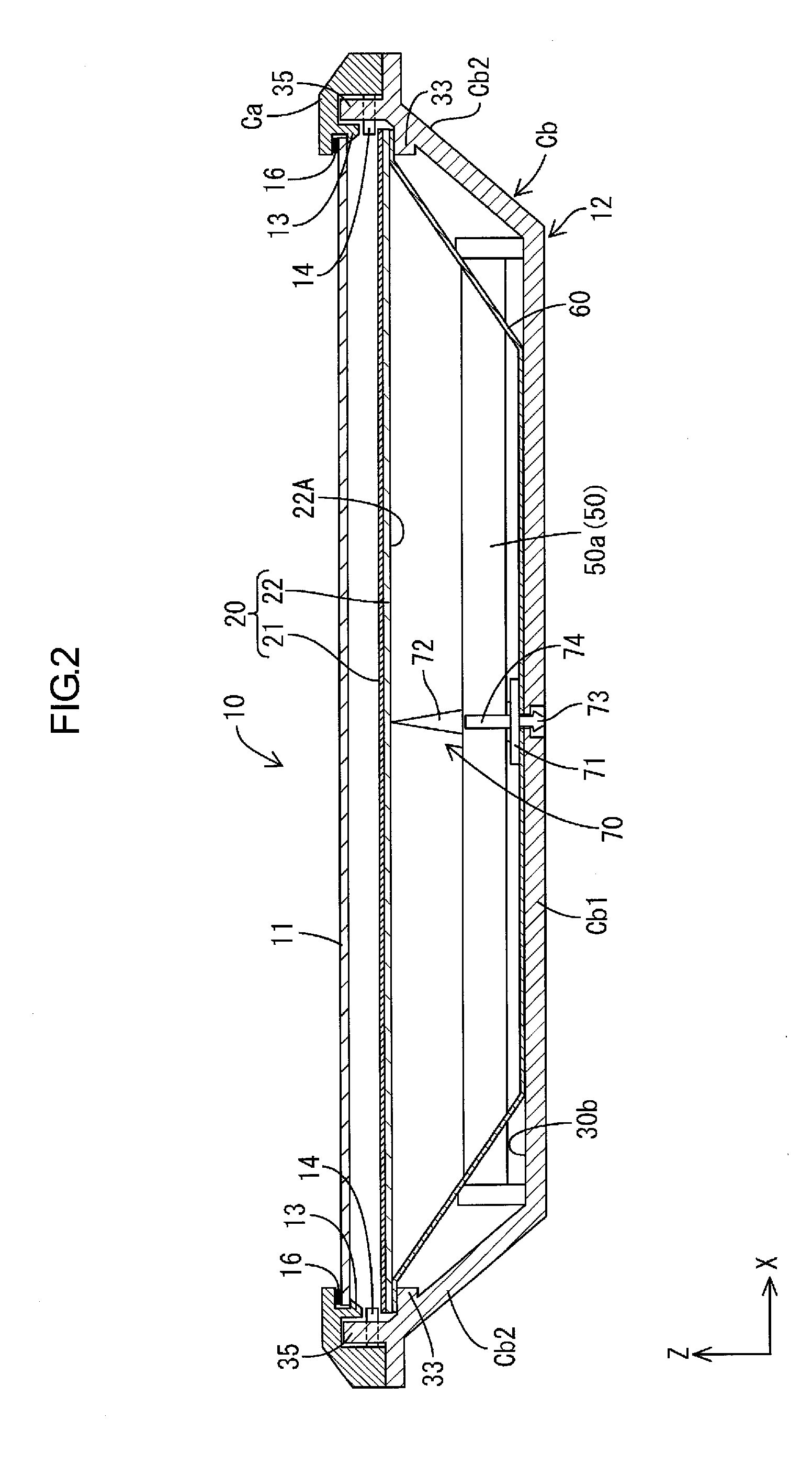
[0007]With this configuration, since the power supply board is arranged in the board housing section, it is possible to arrange the light source and the power supply board side by side respectively in different positions in the longer-side direction or the shorter-side direction of the housing member. As a result, it is possible to reduce the thickness of the housing member (the length in a direction orthogonal to the longer-side direction and the shorter-side direction) as much as possible and reduce the thickness of the lighting device. In order to form the board housing section, for example, a configuration is also conceivable in which the light source is arranged at one end area of the housing ember with respect to the longer-side direction or the shorter-side direction and the other end space is formed as the board housing section. However, in this configuration, since a distance from the light source to the other end area increases, the luminance on the other end area is low compared with the luminance on one end area and luminance unevenness tends to occur. In this regard, in the present invention, since the light source is arranged in the center in the longer-side direction or the shorter-side direction in the housing member, it is possible to suppress luminance unevenness compared with the configuration in which the light source is arranged on one end area. The shorter-side direction of the housing member indicates a short-side direction of the housing member.

Problems solved by technology

However, in this configuration, since a distance from the light source to the other end area increases, the luminance on the other end area is low compared with the luminance on one end area and luminance unevenness tends to occur.

Method used


Image

  • Lighting device, display device, television receiver
  • Lighting device, display device, television receiver
  • Lighting device, display device, television receiver

Examples


first embodiment

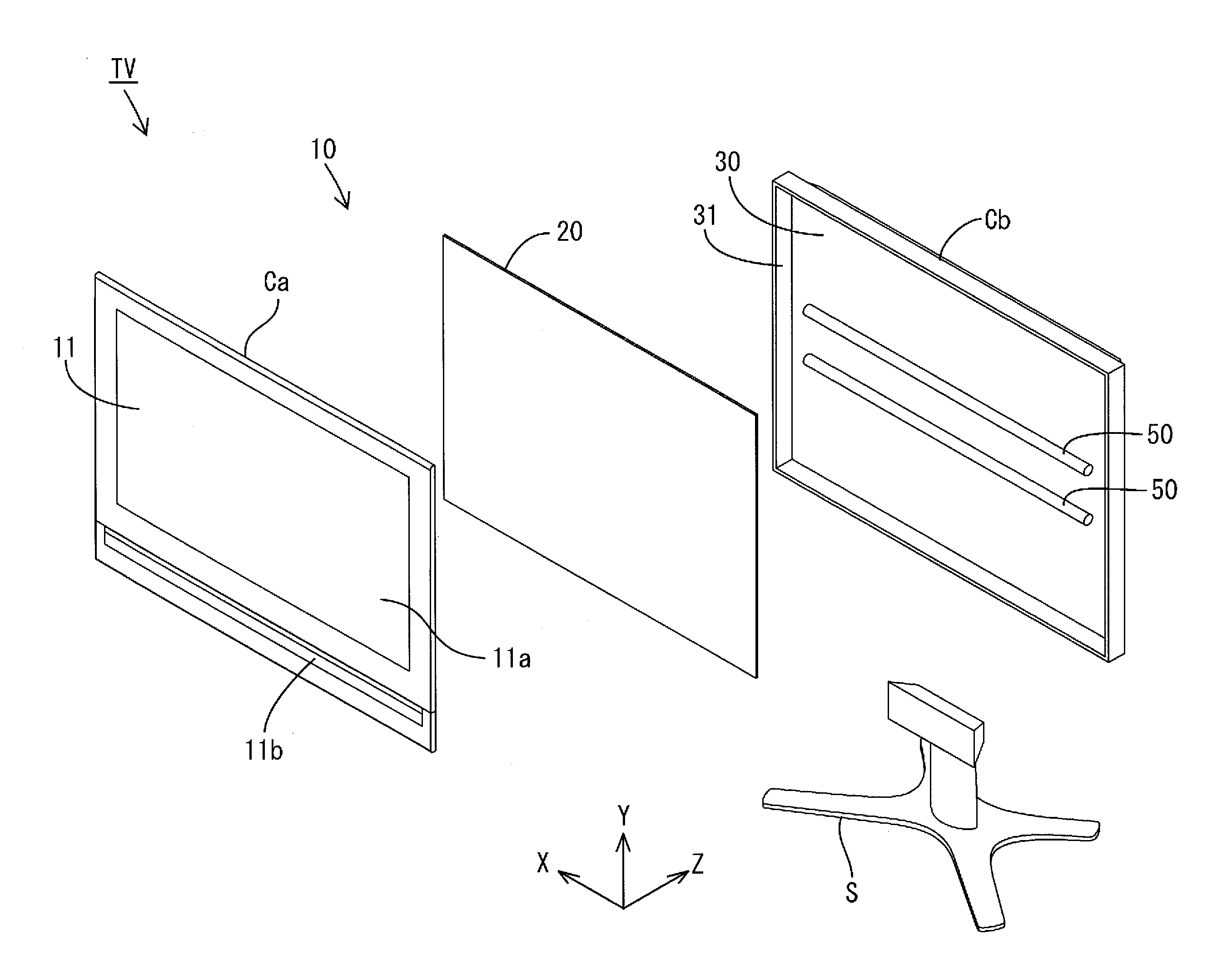
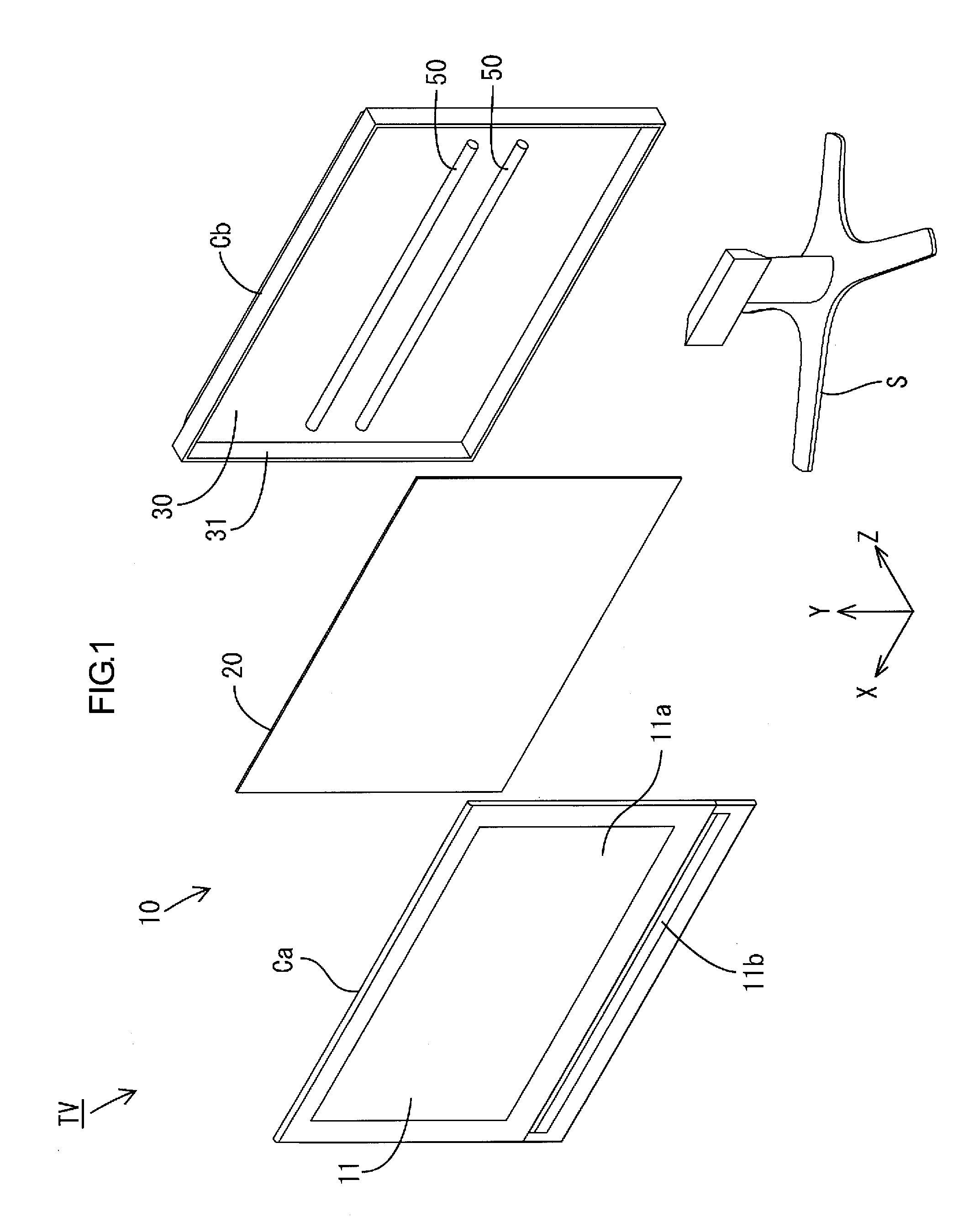
[0020]A first embodiment of the present invention is explained with reference to FIGS. 1 to 8. In this embodiment, an X axis, a Y axis, and a Z axis are shown in a part of the drawings. Axis directions are drawn to be directions shown in the drawings. An upper side shown in FIGS. 2 and 3 is set as a front side and a lower side in the figures is set as a rear side. A television receiver TV according to this embodiment shown in FIG. 1 includes a liquid crystal display device 10, a stand S for placing the liquid crystal display device 10, a not-shown power supply, a not-shown tuner and the like.

[0021]The liquid crystal display device (a display device) 10 is formed in a square shape long in sideways as a whole and supported by the stand S such that a display surface extends along the vertical direction (the Y axis direction). The liquid crystal display device 10 includes a backlight device 12 (a lighting device), which is an external light source, a liquid crystal panel 11 (a display p...

second embodiment

[0051]A second embodiment of the present invention is explained with reference to FIG. 9. A liquid crystal display device 100 according to the second embodiment is different from the first embodiment in a configuration including a sheet supporting member 110 for supporting the reflection sheet 60. In the second embodiment, components having names same as those in the first embodiment are denoted by the same reference numerals and signs and redundant explanation is omitted concerning structures, actions, and effects.

[0052]The sheet supporting member 110 is made of, for example, a synthetic resin and, in plan view, formed in a flat shape having a size substantially the same as the bottom section 60A of the reflection sheet 60. The sheet supporting member 110 is laid on the bottom plate Cb1 in the second cabinet Cb and supports the bottom section 60A of the reflection sheet 60. Since the second cabinet Cb in this embodiment is a member for attaching various components such as the power...

third embodiment

[0053]A third embodiment of the present invention is explained with reference to FIGS. 10 to 12. A liquid crystal display device 200 according to the third embodiment is different from the embodiments explained above in a configuration in which LEDs 221, which are point light sources, are used as the light sources. The lamp clip 70 according to the embodiments is disused and a retaining member 270 is provided. In the third embodiment, components having names same as those in the first embodiment are denoted by the same reference numerals and signs and redundant explanation is omitted concerning structures, actions, and effects.

[0054]In this embodiment, on the bottom surface 30 of the second cabinet Cb, an LED board 220 mounted with plural LEDs 221 is arranged via a sheet supporting member 210. As shown in FIG. 11, the LED board 220 is formed in a rectangular shape long in the X axis direction. The plural LEDs 221 are mounted at an equal interval along the X axis direction. In the LE...


PUM


Abstract

It is an object of the present invention to provide a lighting device that can attain a reduction in thickness. A lighting device according to the present invention includes a hot-cathode tube 50, a circuit board 80, and a second cabinet Cb. The circuit board 80 is configured to supply electric power to the hot-cathode tube 50. The second cabinet Cb has a rectangular shape in plan view and houses the hot-cathode tube 50 and the circuit board 80. The hot-cathode tube 50 is arranged in a center area of the second cabinet Cb with respect to a longer-side direction or a shorter-side direction of the second cabinet Cb to form a board housing section 30b. The board housing section 30b houses the circuit board 80. The board housing section 30b is provided in at least one of outer areas each located on either side of the center area with respect to the longer-side direction or the shorter-side direction in the second cabinet Cb.

Description

TECHNICAL FIELD[0001]The present invention relates to an lighting device, a display device, and a television receiver.BACKGROUND ART[0002]In recent years, display elements of image display devices such as a television receiver are being shifted from the conventional cathode-ray tube to thin display devices to which thin display elements such as a liquid crystal panel and a plasma display panel are applied. This makes it possible to reduce the thickness of an image display device. A liquid crystal panel used for a liquid crystal display device does not spontaneously emit light. Therefore, a backlight is separately required as an lighting device. A backlight described in Patent Literature 1 includes a light source, a housing to which the light source is attached, and an electric circuit for turning on the light source.PRIOR ART DOCUMENTPatent Document[0003]Patent Document 1: Japanese Unexamined Patent Application Publication No. 10-106342PROBLEM TO BE SOLVED BY THE INVENTION[0004]A fu...

Claims


Application Information

Patent Timeline
IPC IPC(8): G02F1/1335G09F13/04F21V21/00F21V15/01F21V7/00F21Y101/00
CPCG02F1/133604G02F2201/465G02F2001/133612G02F1/133611G02F1/133612
Inventor YOKOTA, MASASHI
Owner SHARP KK
Learn More