Eureka AIR delivers breakthrough ideas for toughest innovation challenges, trusted by R&D personnel around the world.

Method and system for indicating overload indicator report

Inactive Publication Date: 2012-04-05
ZTE CORP
View PDF7 Cites 2 Cited by
  • Summary
  • Abstract
  • Description
  • Claims
  • Application Information

AI Technical Summary

Benefits of technology

[0008]In view of this, a main object of the present invention is to provide a method, a terminal and a system for indicating an OI report so as to efficiently decrease overhead of the system.
[0045]In the technical scheme for indicating an OI report in accordance with the present invention, interference states of all PRBs occupied by a RS or UT are normalized to obtain an average interference level; the average interference level is used as an OI level resetting threshold to divide levels of the OI. Thus, no matter how many levels the original OI has, after the levels are reset, the OI is divided into only two levels, and the interference states of the PRB also are divided into two states based on the levels of the OI. Therefore, only 1 bit is needed to represent the interference states of the PRB, thus greatly reducing the length of the OI report and saving overhead of the system.

Problems solved by technology

In then ext generation wideband communication system, solving inter-cell interference becomes a key factor to improve throughput and average UT throughput of a user terminal (UT), and how to efficiently solve inter-cell interference faces a severe challenge.
However, since there are four representation modes, namely, “11”, “10”, “01” and “00” for 2 bits, which may be used to represent four interference states, and only three interference states are used in the LTE system, one state will be wasted.
Therefore, the LTE system fails to efficiently use resources of 2 bits in representing interference states of the PRB, thus causing waste of system resources and increasing overhead of the system.

Method used


Image

  • Method and system for indicating overload indicator report
  • Method and system for indicating overload indicator report
  • Method and system for indicating overload indicator report

Examples


Embodiment Construction

[0052]The technical scheme of the present invention will be further described in detail below in conjunction with the accompanying drawings and the specific embodiments.

[0053]A method for indicating an OI report in accordance with the present invention is applicable to both a typical wireless communication network and a wireless communication network with a relay station (RS). The method for indicating the OI report in accordance with the present invention comprises two portions, one is an indicating method for determining the OI report used by a second terminal by using a BS as a first terminal, wherein the second terminal may be a RS or a UT; the other one is an indicating method for determining the OI report used by a second terminal UT through a first terminal, wherein the second terminal may be a BS or a RS.

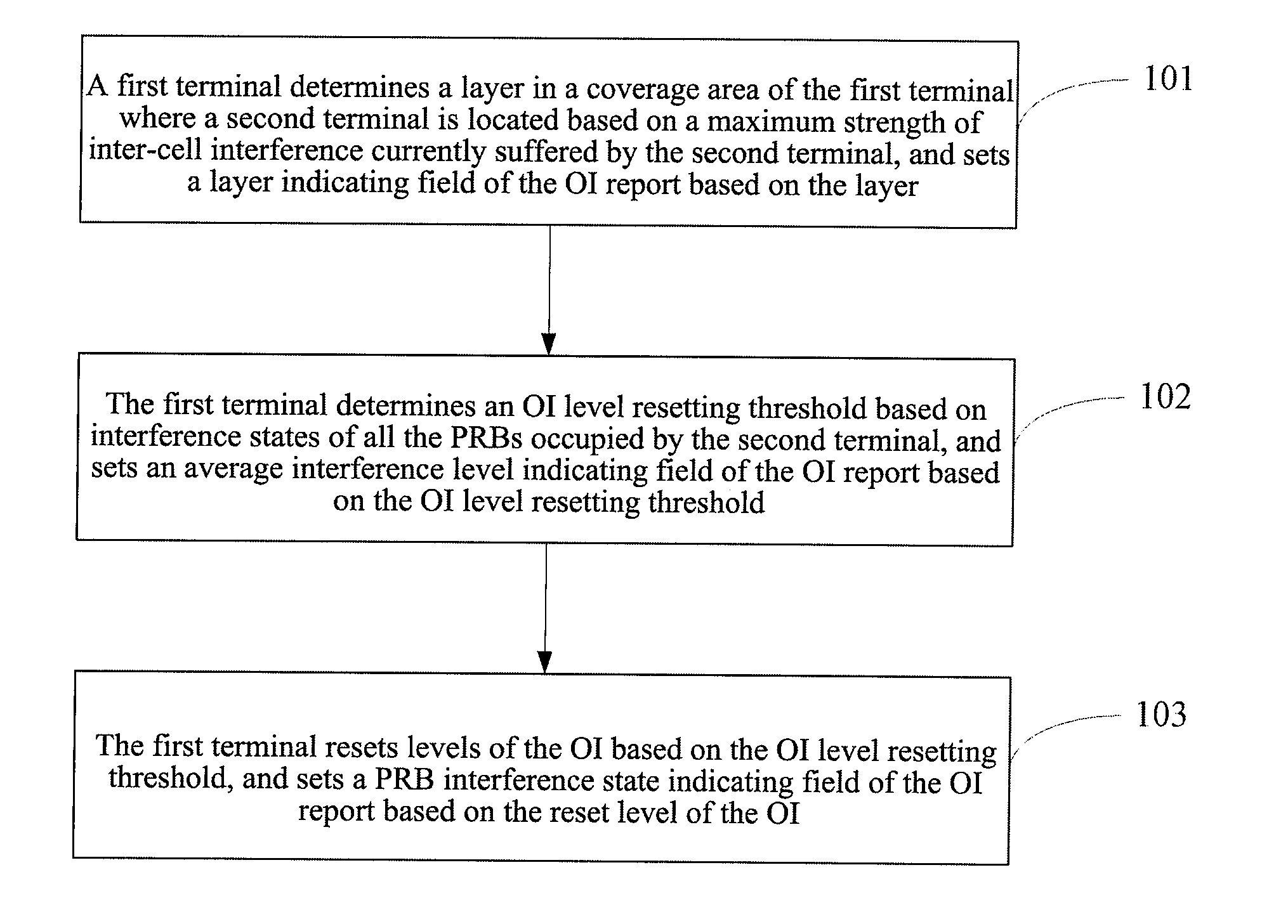
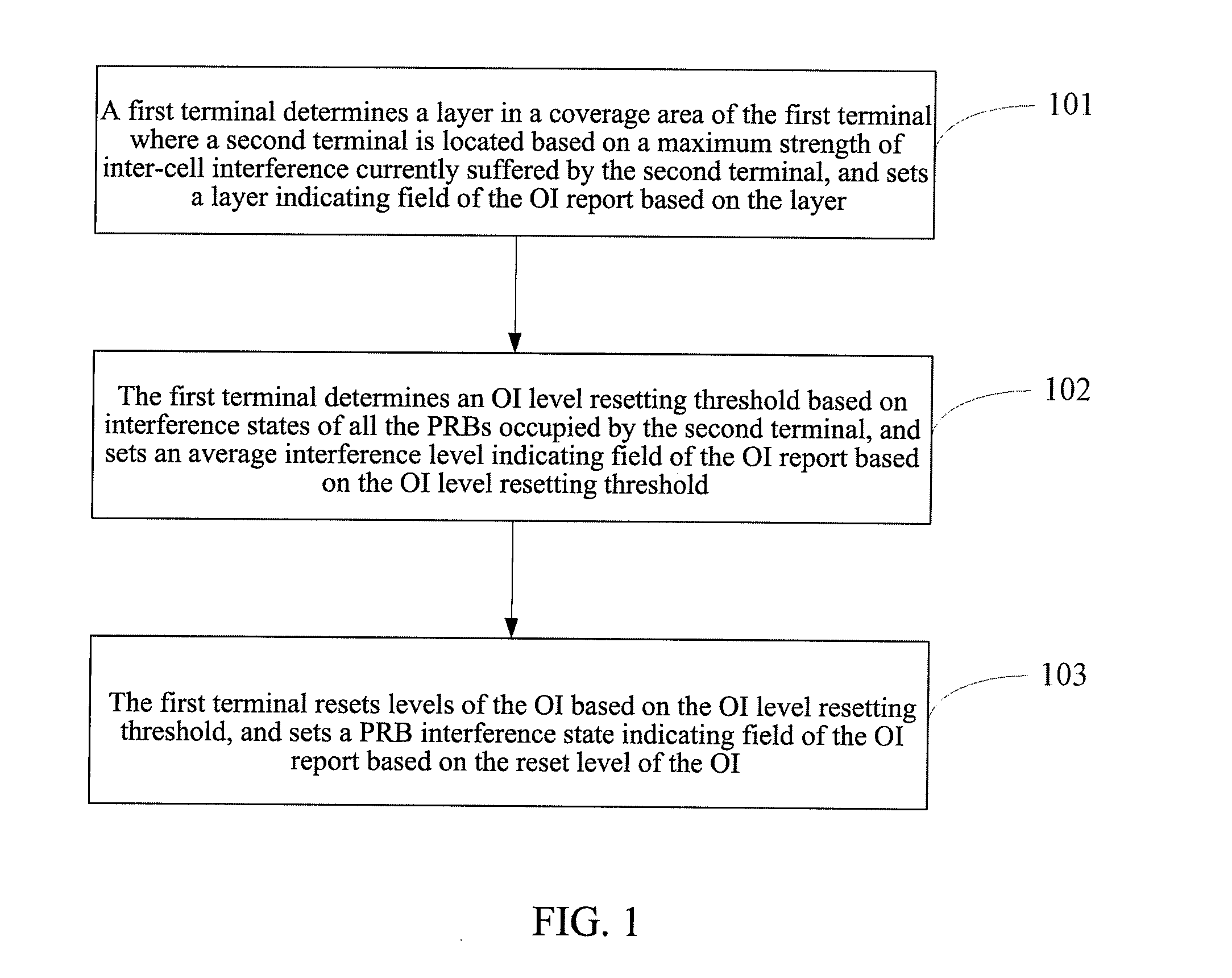
[0054]FIG. 1 illustrates a flow chart of a method for indicating an OI report in accordance with the present invention comprising the following steps.

[0055]Step 101, a first...


PUM


Abstract

The present invention discloses a method for indicating an overload indicator (OI) report comprising: a first terminal determining a layer in a coverage area of the first terminal where a second terminal is located, and setting a layer indicating field of the OI report based on the layer; the first terminal determining an OI level resetting threshold, setting an average interference level indicating field of the OI report based on the OI level resetting threshold; and the first terminal resetting levels of the OI based on the OI level resetting threshold, and setting a physical resource block interference state indicating field of the OI report based on the reset levels of the OI. The present invention discloses a system for indicating an overload indicator (OI) report. Based on the method and system, the overhead of the system can be decreased efficiently.

Description

TECHNICAL FIELD[0001]The present invention relates to an inter-cell interference technology in the field of wireless communication, and in particular, to a method and a system for indicating an overload indicator (OI) report in solving inter-cell interference.BACKGROUND ART[0002]In then ext generation wideband communication system, solving inter-cell interference becomes a key factor to improve throughput and average UT throughput of a user terminal (UT), and how to efficiently solve inter-cell interference faces a severe challenge.[0003]Currently, the IEEE (Institute of Electrical and Electronics Engineers) 802.16j, advanced International Mobile Telecommunications (IMT-Advanced) system and WINNER propose to solve the problem of inter-cell interference by using methods such as interference randomization, interference coordination, interference elimination, etc. The LTE (Long Term Evolution) system, based on the methods described above, proposes to divide the coverage area of the cur...

Claims


Application Information

Patent Timeline
IPC IPC(8): H04L12/26
CPCH04W24/10H04W72/082H04W72/541
Inventor WEI, WEI
Owner ZTE CORP
Why Eureka
Eureka Blog
Learn More