Wireless network and terminal, and network configuration method and device

a wireless network and terminal technology, applied in the field of wireless networks, can solve the problems of increasing power consumption at the nodes, constant power consumption of the receiving component, and inability to change the role of each wireless terminal (relaying or non-relaying), and achieve the effect of reducing the overall power consumption of the wireless network

Inactive Publication Date: 2012-04-05
OKI ELECTRIC IND CO LTD
View PDF4 Cites 24 Cited by
  • Summary
  • Abstract
  • Description
  • Claims
  • Application Information

AI Technical Summary

Benefits of technology

[0009]An object of the present invention is to reduce overall power consumption in a wireless network while ensuring reliable communication.
[0016]The nodes that are selected as parent nodes of other nodes in the network function as relaying nodes. Giving preference to nodes with other child nodes for selection as parent nodes reduces the number of relaying nodes in the network and increases the number of non-relaying nodes, as compared with selection of parent nodes solely on the basis of the received selection values.
[0017]Non-relaying nodes can conserve power by transmitting and receiving only at designated times and operating in a low-power mode at other times. Increasing the number of non-relaying nodes therefore reduces the total power consumption of the network.
[0018]Network communication is reliable because any node can be selected as a parent node and operate as a relaying node. When a failure occurs, the network can reconfigure itself by making new parent node selections.

Problems solved by technology

This assumption, however, leads to increased power consumption at the nodes.
Because each node may receive signals from any of its neighboring nodes, the receiving component of the node must be kept operating and ready to receive at all times, so the receiving component constantly consumes power.
The role of each wireless terminal (relaying or non-relaying) is fixed, however, and cannot be changed.
This creates a problem if a new wireless terminal is added to the network in a position where the only neighboring wireless terminals are non-relaying wireless terminals.
Similar problem are apt to occur if a relaying wireless terminal drops out of the network, or if a link between a relaying wireless terminal and another wireless terminal becomes inoperable.
This makes the network vulnerable to battery failure and various other types of failure that may leave some non-relaying wireless terminal unable to communicate with any relaying wireless terminal.
Such a network lacks reliability.

Method used


Image

  • Wireless network and terminal, and network configuration method and device
  • Wireless network and terminal, and network configuration method and device
  • Wireless network and terminal, and network configuration method and device

Examples


first embodiment

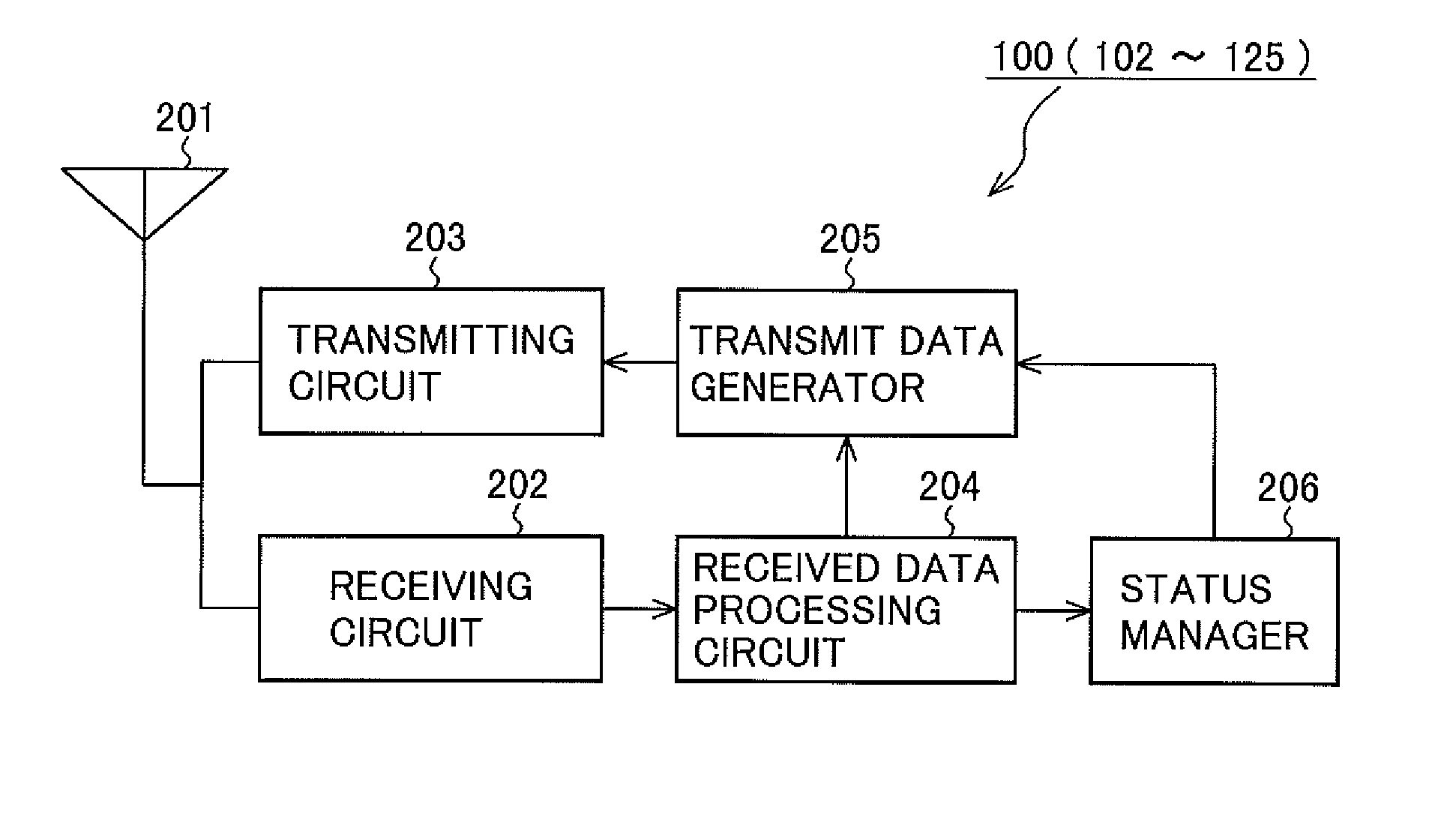
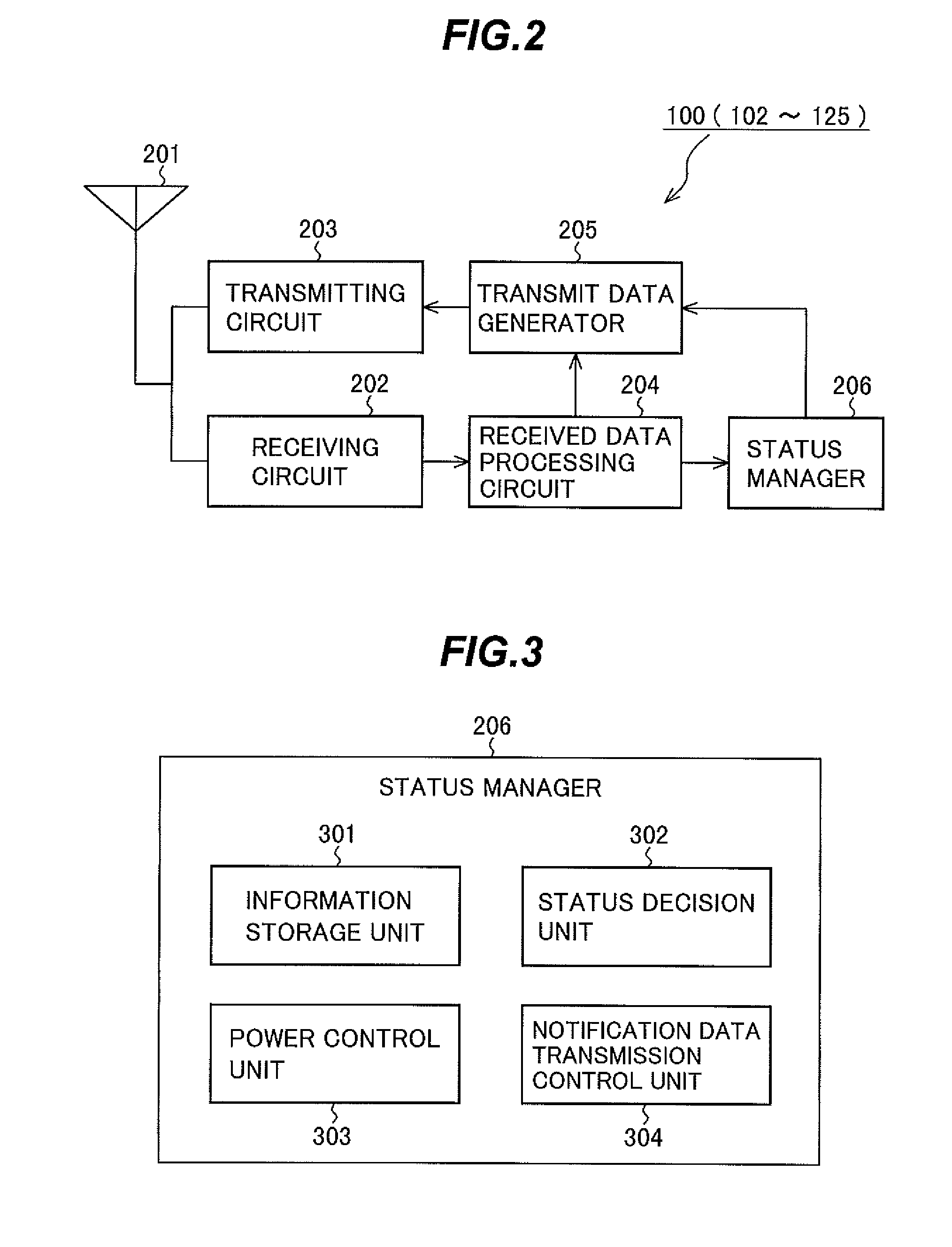
[0035]In the first embodiment, the wireless terminals constituting the wireless network configure the network by executing a parent terminal decision program installed in each wireless terminal. The wireless network in this embodiment may be any type of wireless multi-hop network that can operate with a tree topology. A particular example is a sensor network.

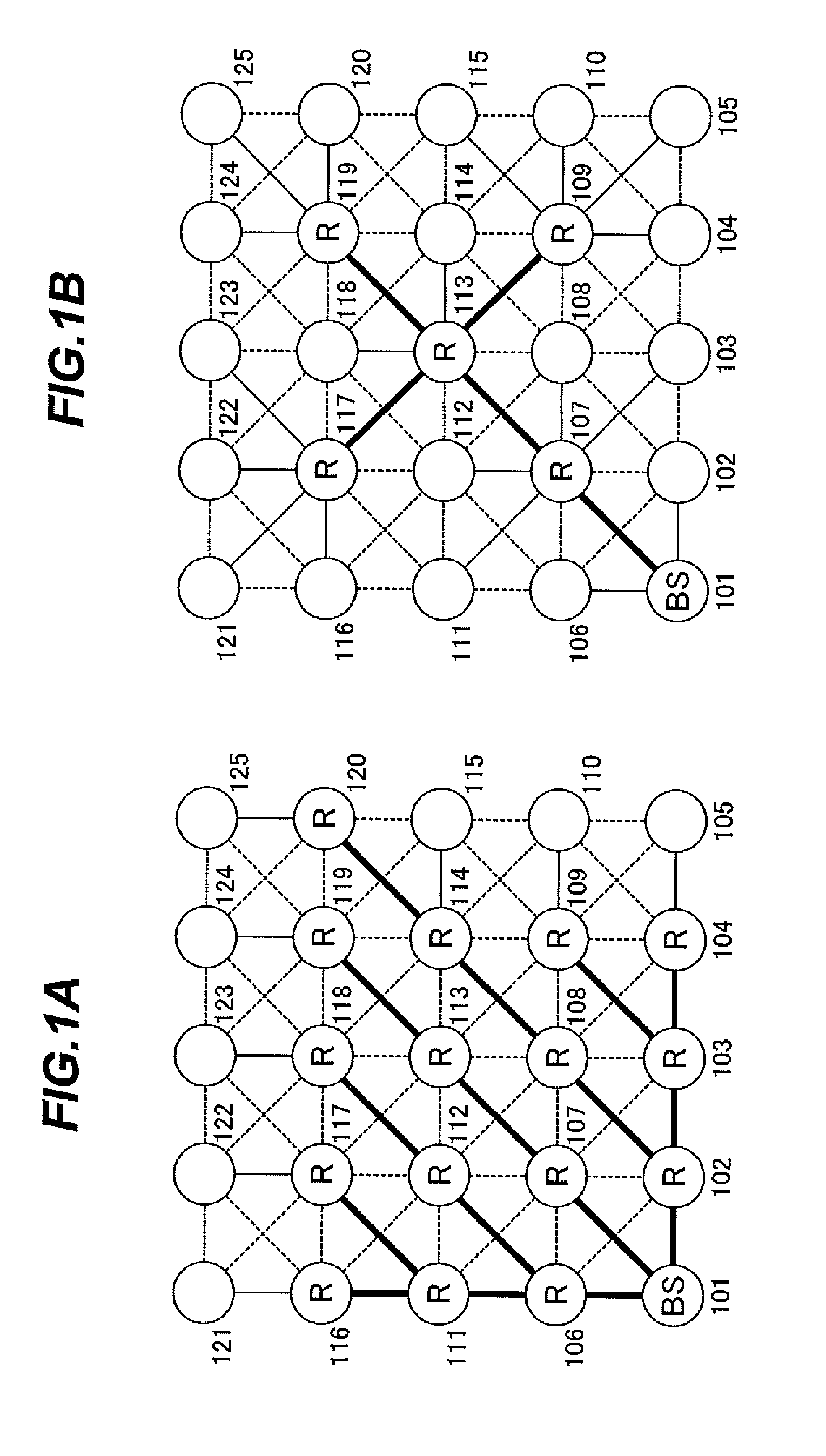
[0036]FIGS. 1A and 1B are two examples of wireless networks with identical numbers (twenty-five) of wireless terminals (also referred to as nodes below) 101 to 125 and identical physical layouts but different tree topologies. In both topologies wireless terminal 101 is the root node and functions as a base station (BS) through which the network is connected on a constant basis to an external network. The wireless terminals indicated by the letter R operate as relaying nodes, and are referred to as routers below. In the wireless network in FIG. 1A, there are sixteen routers 102-104, 106-109, 111-114, and 116-120. In the wireless ...

second embodiment

[0104]The wireless terminal, parent-node decision method, and wireless network in a second embodiment will now be described.

[0105]The second embodiment differs from the first embodiment in how a wireless terminal or node chooses its parent node.

[0106]In this embodiment, as in the first embodiment, each wireless terminal or node in the wireless network transmits and receives status notification data and cost notification data, as well as communication data. The only costs considered in the second embodiment, however, are the basic path and link costs, as shown in FIG. 7; there are no additional costs such as the first, second, and third added costs used in the first embodiment.

[0107]The second embodiment lets each node choose its parent node on the basis of four principles: 1) avoid choosing a node having no child node if possible; 2) prefer a node having more child nodes; 3) prefer a node having more neighboring nodes; 4) prefer a node with a smaller cost. Any procedure may be used ...

third embodiment

[0116]The wireless terminal, parent-node decision method, and wireless network in a third embodiment will now be described.

[0117]Whereas a wireless terminal chooses a single parent node in the first and second embodiments, it chooses two parent nodes in the third embodiment. One of the two parent nodes is an active parent node that is used normally, while the other is a back-up parent node that substitutes for the active parent node if a malfunction occurs at the active parent node or communication with the active parent node is lost.

[0118]The reason for choosing active and back-up parent nodes simultaneously in the third embodiment is as follows.

[0119]In the first and second embodiments, since each wireless terminal chooses only one parent node, if it loses contact with its chosen parent node for any reason, it must choose another parent node to serve as its router. The first and second embodiments minimize the number of routers, however, so there is a reduced probability that any ...


PUM


Abstract

A tree topology in a multi-hop wireless network is configured by having each node other than the root node select a parent node within direct communication range, thereby becoming a child node of the selected parent node. Neighboring nodes provide selection values such as routing costs and local structural information indicating the existing topology in their vicinities, including parent-child relationships. The selection of the parent node is based on the received selection values, but the local structural information is used to bias the selection in favor of neighboring nodes with at least one other child node. This selection strategy reduces the number of parent nodes in the network and enables more nodes to operate as end nodes, which can then conserve power by carrying out sleep control.

Description

BACKGROUND OF THE INVENTION[0001]1. Field of the Invention[0002]The present invention relates generally to a wireless network such as sensor network with a tree topology, and more particularly to the selection of parent nodes in the network.[0003]2. Description of the Related Art[0004]Various methods have been developed for configuring a wireless network in which nodes that are not directly linked communicate in a series of hops through intermediate nodes. Unlike wireline networks, wireless networks permit a node to transmit signals to all its neighboring nodes with no additional wiring cost, so the multi-hop communication routes are often selected on the assumption that each node can communicate with all its neighboring nodes.[0005]This assumption, however, leads to increased power consumption at the nodes. Because each node may receive signals from any of its neighboring nodes, the receiving component of the node must be kept operating and ready to receive at all times, so the rec...

Claims


Application Information

Patent Timeline
Patent Type & Authority Applications(United States)
IPC IPC(8): H04W84/00
CPCH04W84/18Y02B60/50H04W88/04Y02D30/70
Inventor YANAGIHARA, KENTAROUNISHIMURA, HIROSHIKUBO, YUKINOZAKI, MASANORI
Owner OKI ELECTRIC IND CO LTD
Why Eureka
Try Eureka