Locking wedge system
a wedge system and locking wedge technology, applied in the direction of threaded fasteners, fastening means, screws, etc., can solve the problems of unsuitable for such locking torque, unsuitable for standard hand tools, and inability to achieve the desired fastening effect, so as to reduce the requirement for access space, the effect of reducing the requirement of strain energy and increasing the length
- Summary
- Abstract
- Description
- Claims
- Application Information
AI Technical Summary
Benefits of technology
Problems solved by technology
Method used
Image
Examples
first embodiment
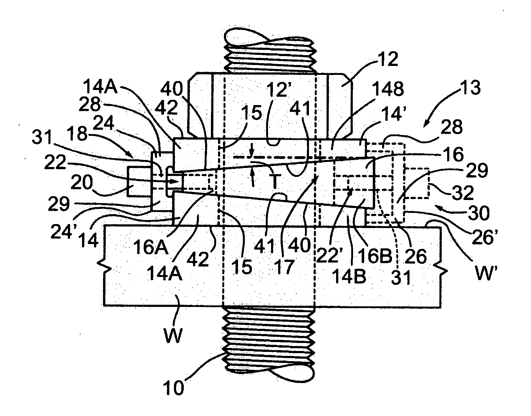
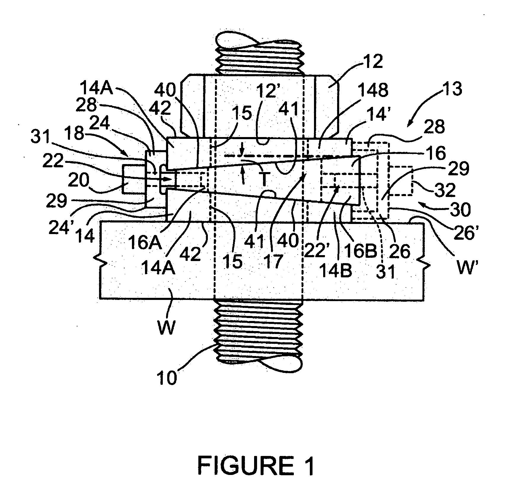
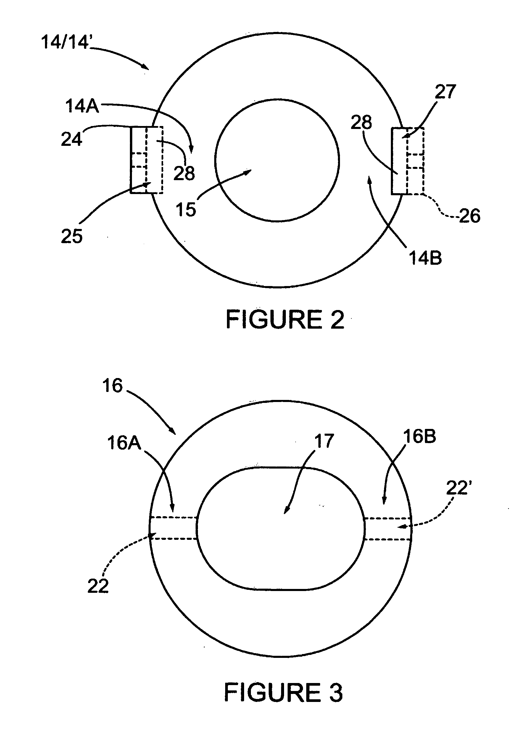
[0094]Referring to FIG. 1, in this first embodiment a threaded workpiece W is threaded onto a threaded stud 10, having a locknut 12 threaded onto the stud 10, in axially spaced relation with the workpiece W. Interposed between the nut 12 and the workpiece W is a subject locking wedge system 13 having a pair of tapered washers 14, 14′, each having a washer aperture 15 with a clearance fit for mounting on stud 10. Tapered washers each have an angle of taper T. The inner face 12′of the nut 12 and inner face W′ of workpiece W bear against the adjoining outer faces 42, of tapered washers 14, 14′. The washers 14, 14′ are separated by a tapered wedge member 16, having opposing faces 40 that each have cooperating angle of taper T, the same as the angle of taper T of the cooperating inner faces of tapered washers 41 of tapered washers 14, 14′. The outer faces of tapered washers 42 of tapered washers 14, 14′ are typically, but do not necessarily need to be, normal to the polar axis of the thr...
second embodiment
[0104]Turning to the FIGS. 4 and 5, in this second embodiment of the locking wedge system, tapered washers 43, 43′ have shouldered locking recesses 50, to receive and contain locking push abutment 52, that slide longitudinally into the shouldered locking recesses 50 which straddle spaced tapered washers 43, 43′ to position the threaded bore 33 in bridge portion 29 of the locking push abutment 52 in aligned relation with the centering recess 58 in thicker end face 49 of tapered wedge member 44 (shown in phantom in FIG. 4).
[0105]A locking jacking screw 54 (with rounded tip), in threaded relation through threaded bore 33 in bridge portion 29 of locking push abutment 52, has a rounded tip 56 that enters corresponding rounded locking centering recess 58, located in the thicker end face 49 of the tapered wedge member 44 to provide wedging action against the washers 43, 43′. It is to be understood that rounded tip 56 and corresponding rounded locking centering recess 58 are preferred but n...
PUM
 Abstract
Description
Claims
Application Information
 - R&D
- Intellectual Property
- Life Sciences
- Materials
- Tech Scout
- Unparalleled Data Quality
- Higher Quality Content
- 60% Fewer Hallucinations
Browse by: Latest US Patents, China's latest patents, Technical Efficacy Thesaurus, Application Domain, Technology Topic, Popular Technical Reports.
© 2025 PatSnap. All rights reserved.Legal|Privacy policy|Modern Slavery Act Transparency Statement|Sitemap|About US| Contact US: help@patsnap.com


