Image processing apparatus, method for processing image, and storage medium therefor

a technology of image processing and apparatus, applied in the direction of electrographic process apparatus, visual presentation, instruments, etc., can solve the problems of aging of apparatus components, affecting the quality of images, so as to reduce the amount of recording materials

Active Publication Date: 2012-04-12
CANON KK
View PDF4 Cites 19 Cited by
  • Summary
  • Abstract
  • Description
  • Claims
  • Application Information

AI Technical Summary

Benefits of technology

[0012]The present invention relates to an image processing apparatus capable of appropriately setting a limit value of a recording material according to the state of the image processing apparatus without excessively reducing the recording material amount, a method for processing an image, and a storage medium therefor.
[0014]According to the present invention, it is possible to appropriately set the limit value of the recording material according to the state of the image processing apparatus without excessively reducing the recording material amount.

Problems solved by technology

Conventionally, when an image forming unit employs the electrophotographic method, electrophotographic processes such as laser exposure, latent image formation on a photosensitive member (drum), image development by toner, toner image transfer onto paper, and image fixing by heat are susceptible to the apparatus ambient temperature and humidity as well as to aging of apparatus components.
In this case, restraining an upper-limit density may cause a problem that jaggies or discontinuities of images are produced when outputting texts and thin lines having the maximum density.
Meanwhile, if the amount of recording material such as toner and ink exceeds a certain fixed amount per unit area, inferior fixing or scattering of toner may occur possibly causing degradation in image quality as well as damage to the apparatus.
However, as described above, if an output exceeds the target maximum density of the apparatus to reduce jaggies under the situation that the upper-limit recording material amount per unit area is predetermined, image defects such as inferior fixing and scattering of recording material may occur.
This case will cause excessive recording material.
If a toner amount limit is set in a small value by estimating much increase in density of the image, when an image to be printed has a low density, a toner amount may be excessively reduced depending on the printer characteristics.

Method used


Image

  • Image processing apparatus, method for processing image, and storage medium therefor
  • Image processing apparatus, method for processing image, and storage medium therefor
  • Image processing apparatus, method for processing image, and storage medium therefor

Examples


Embodiment Construction

[0031]Various exemplary embodiments, features, and aspects of the invention will be described in detail below with reference to the drawings.

[Configuration of Image Processing Apparatus]

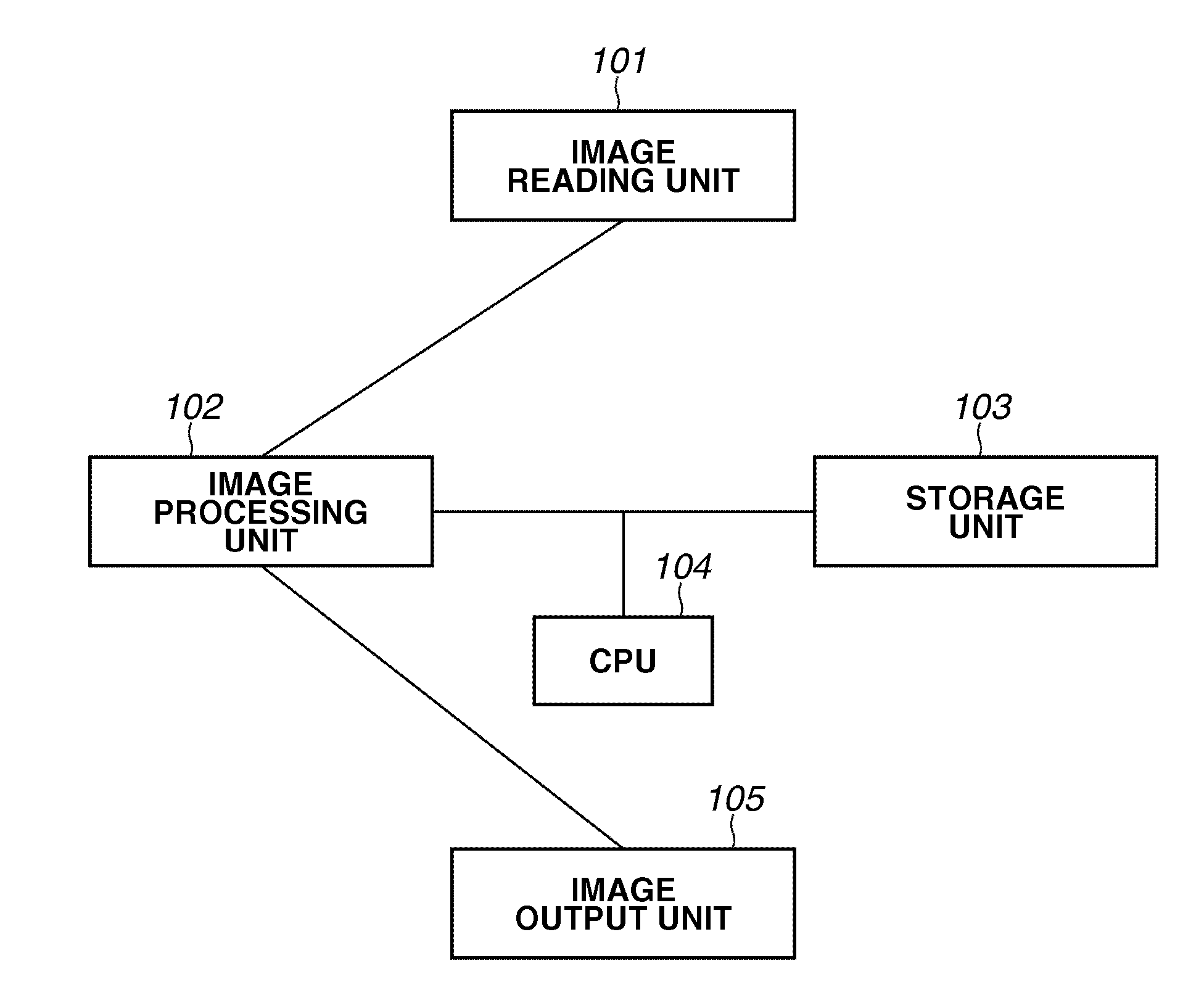
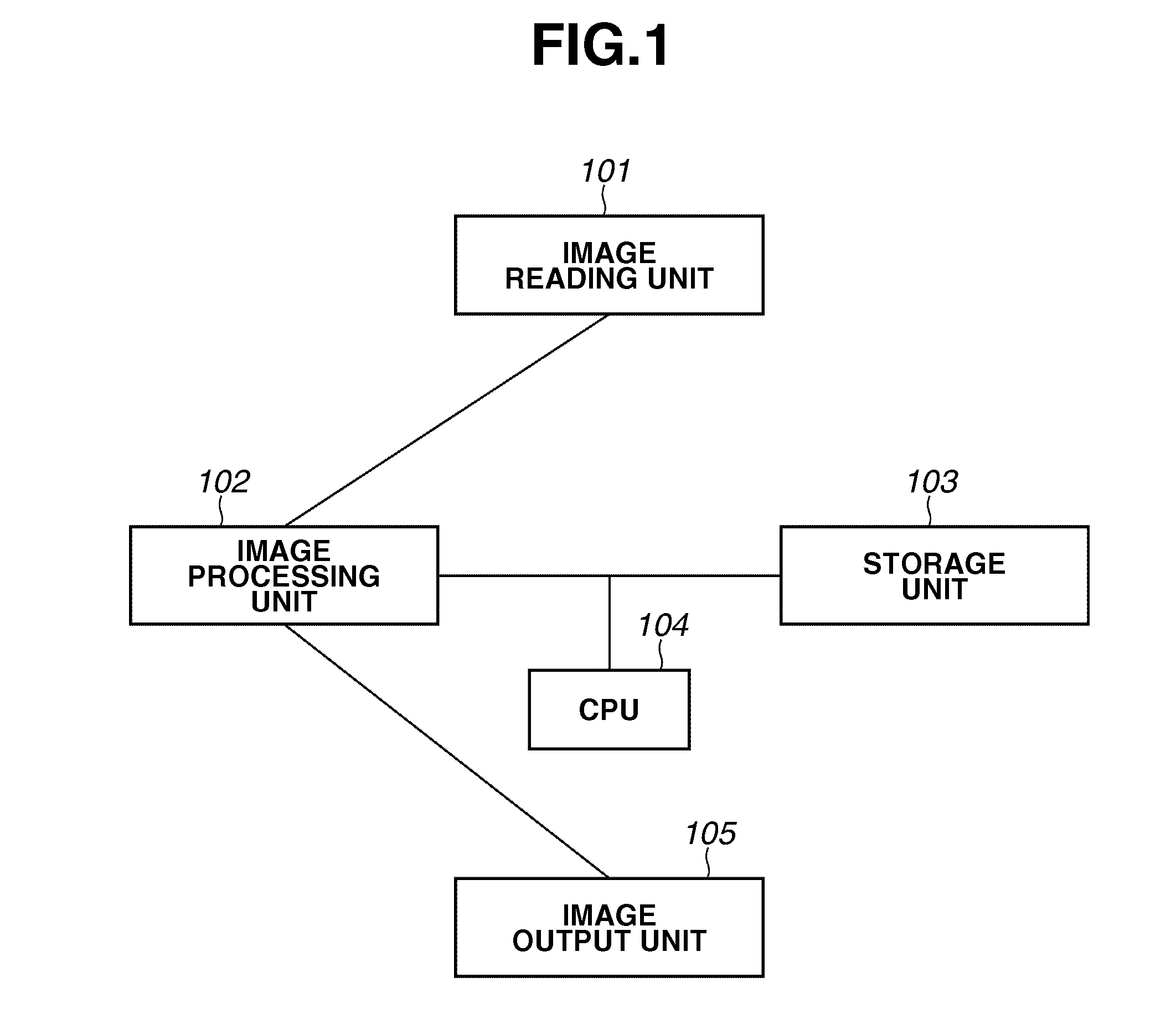
[0032]FIG. 1 is a block diagram illustrating a configuration of an image processing apparatus according to first, second, and third exemplary embodiments. As illustrated in FIG. 1, the image processing apparatus includes an image reading unit 101, an image processing unit 102, a storage unit 103, a central processing unit (CPU) 104, and an image output unit 105. The image processing apparatus is connectable with a server for managing image data and a personal computer (PC) for instructing execution of printing via a network. The image reading unit 101 reads a document image and outputs relevant image data.

[0033]The image processing unit 102 converts print information including image data input from the image reading unit 101 or outside into intermediate information, applies image correction such as d...


PUM


Abstract

A limit value of a recording material is determined based on a difference between a maximum density value of an image formed by an image forming unit and a maximum density value to be targeted by an image processing apparatus, and the amount of the recording material corresponding to the image data is controlled so as to be the determined limit value or below.

Description

BACKGROUND OF THE INVENTION[0001]1. Field of the Invention[0002]The present invention relates to an image processing apparatus, a method for processing an image, and a storage medium therefor.[0003]2. Description of the Related Art[0004]The electrophotographic method is known as an image recording method used for image processing apparatuses such as printers and copying machines. The electrophotographic method forms a latent image on a photosensitive drum by using a laser beam and develops the latent image by a charged color material (hereinafter referred to as toner) to form a toner image. To record an image, the electrophotographic method transfers the developed toner image onto a transfer sheet and then fixes the transferred image.[0005]Conventionally, when an image forming unit employs the electrophotographic method, electrophotographic processes such as laser exposure, latent image formation on a photosensitive member (drum), image development by toner, toner image transfer ont...

Claims


Application Information

Patent Timeline
Patent Type & Authority Applications(United States)
IPC IPC(8): G06K15/00H04N1/40
CPCG03G15/011G03G15/5062G03G21/02H04N1/6033H04N1/1017H04N1/6022G03G2215/00029
Inventor TAMURA, HIROKAZU
Owner CANON KK
Why Eureka
Try Eureka