Cooling structure for rotary electric machine

a technology of rotary electric machines and cooling structures, which is applied in the direction of dynamo-electric machines, support/enclosement/cases, and magnetic circuit shapes/forms/constructions, etc., can solve the problems of difficult pipe connection, inability to obtain cooling performance and thus insulating performance, and uneven pressure and amount of cooling oil supplied to the oil chambers, so as to improve the assemblability and mountability of the rotary electric machine

Active Publication Date: 2012-04-19
TOYOTA JIDOSHA KK +1
View PDF27 Cites 27 Cited by
  • Summary
  • Abstract
  • Description
  • Claims
  • Application Information

AI Technical Summary

Benefits of technology

[0022]With the cooling structure for a rotary electric machine according to this aspect, the coolant supply port for supplying coolant to the first coolant chamber via the first coolant supply path and to the second coolant chamber via the second coolant supply path is formed on a side of one of the lead side cover member and the non-lead side cover member. Therefore, the work of connecting the coolant supply conduit in a fluid-tight manner to the coolant supply port of the rotary electric machine that includes this cooling structure can be easily performed from one direction, which both improves assemblability of the rotary electric machine and mountability when mounting this kind of rotary electric machine to a vehicle.

Problems solved by technology

In this case, when an oil chamber is formed for each coil end portion on both sides in the axial direction using the cooling jacket of a similar shape and cooling oil is supplied into each oil chamber from the oil supply ports provided on both sides in the axial direction, the pressures and amounts of cooling oil supplied to the oil chambers may become uneven due to a difference in the size of the coil end portions or the like.
As a result, even cooling performance, and thus insulating performance, in the coil end portions may not be able to be obtained.
Therefore, when attempting to connect oil supply pipes to the oil supply ports formed pointing in opposite directions as described above when assembling a motor-generator as a power supply for running that incorporates this cooling structure to a transmission, the assembly posture, the assembly space, and the work space and the like of the motor-generator may make it difficult to connect the pipe.
In this case, it is difficult to connect the oil supply pipes while checking the seal of each oil supply port.
In particular, if a motor-generator is mounted to an electric vehicle and the motor mounting space is set far back and is narrow and there is no work space for an assembly worker on either side in the axial direction of the motor, assemblability of the motor provided with this cooling structure into the vehicle is poor.

Method used


Image

  • Cooling structure for rotary electric machine
  • Cooling structure for rotary electric machine
  • Cooling structure for rotary electric machine

Examples


Embodiment Construction

[0045]Hereinafter, example embodiments of the invention will be described in detail with reference to the accompanying drawings. In the description, the specific shapes, materials, numeric values, and directions and the like are merely examples to facilitate understanding of the invention, and may be changed as appropriate according to the use, objective, and specifications and the like.

[0046]In the description below, coolant used with the cooling structure for a rotary electric machine according to this example embodiment is described as being cooling oil, but the coolant of the cooling structure of this invention is not limited to this. For example, other coolant such as LLC may be used.

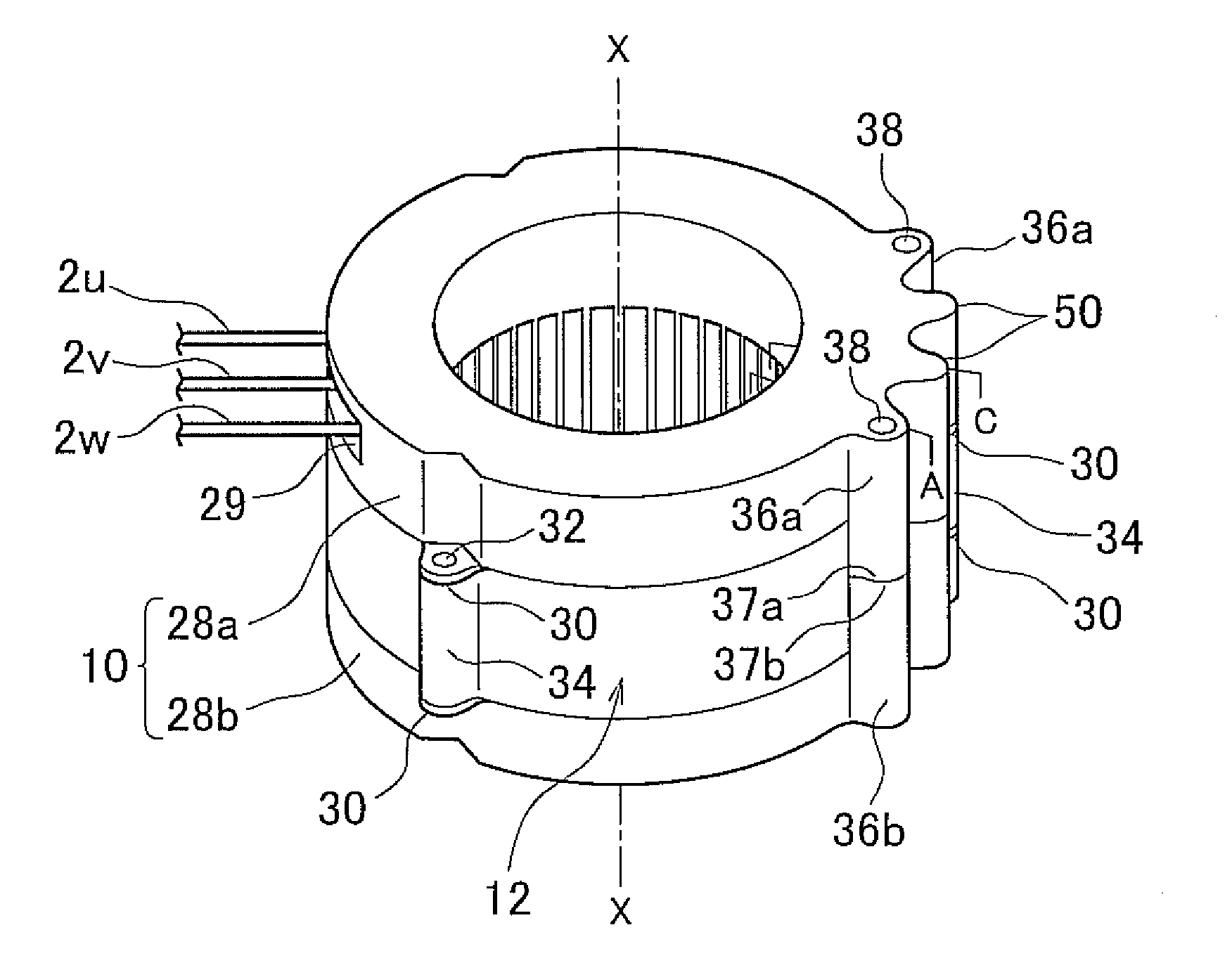
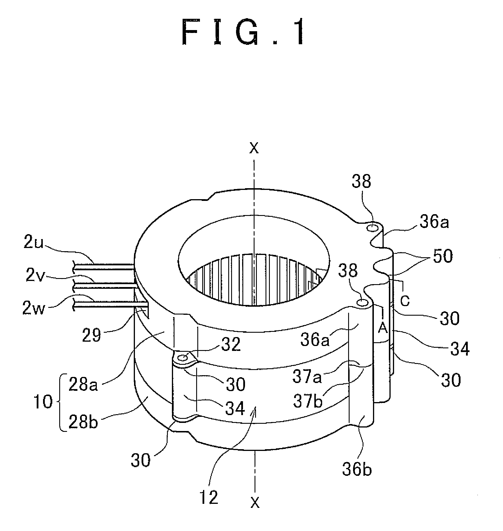
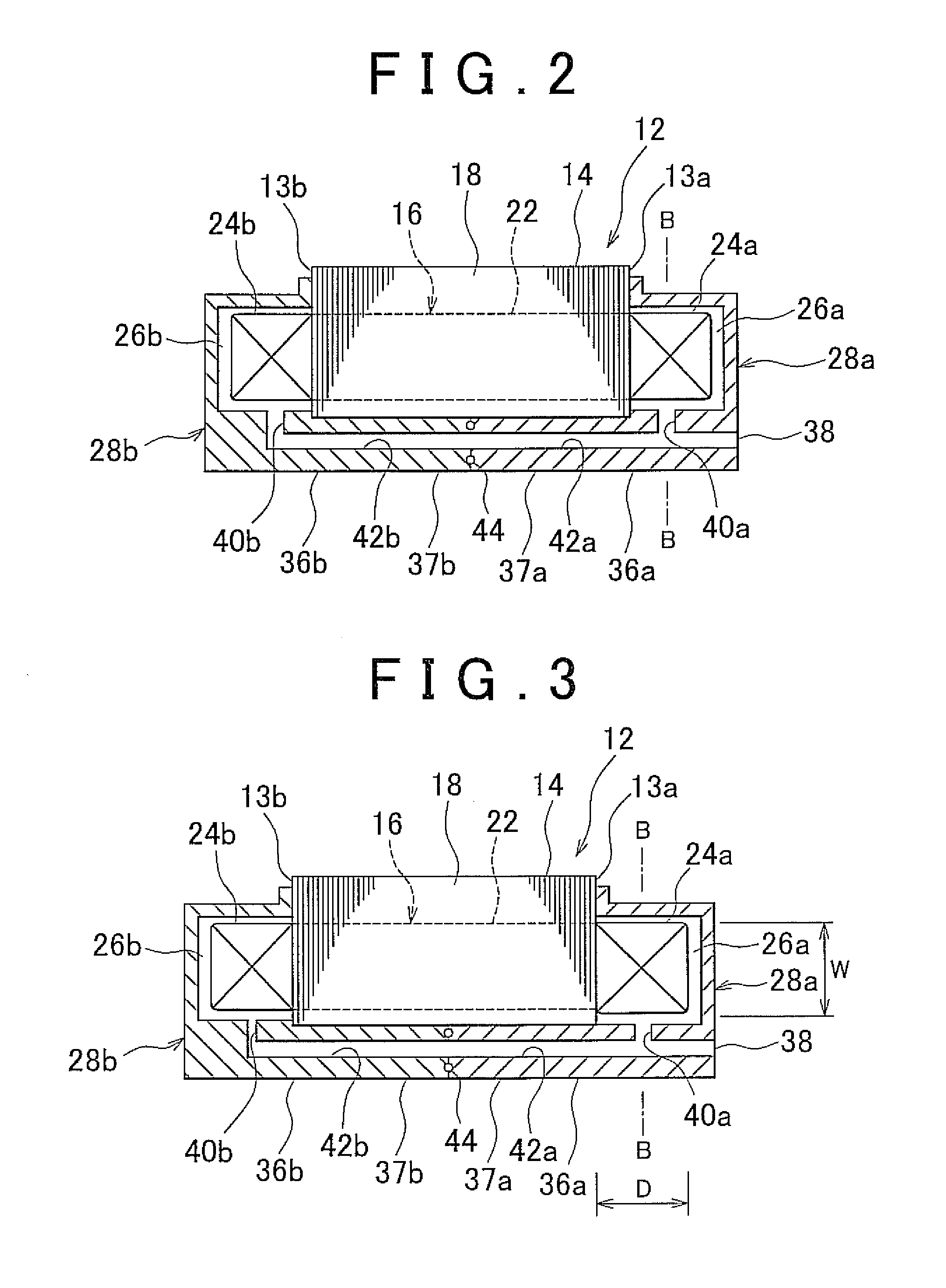
[0047]A first example embodiment of the invention will now be described. FIG. 1 is a perspective view of a cooling structure 10 for a rotary electric machine according to this example embodiment that is mounted to a stator 12 for the rotary electric machine. FIG. 2 is a sectional view taken along l...


PUM


Abstract

A cooling structure for a rotary electric machine uses coolant to cool coil end portions that protrude outward, one from each end surface of a stator core, in a stator that includes a stator core and coils that are wound in a circumferential direction of the stator core. This cooling structure includes a lead side cover member that covers a lead side coil end portion to which a lead wire that supplies electricity to the coils is connected, and forms a first coolant chamber within which coolant is stored; and a non-lead side cover member that covers a non-lead side coil end portion positioned opposite the lead side coil end portion in the axial direction, and forms a second coolant chamber within which coolant is stored. A coolant communicating path is provided that communicates the first and second coolant chambers in a manner that enables coolant to flow therebetween.

Description

INCORPORATION BY REFERENCE[0001]This patent application claims the priority to Japanese Patent Application No. 2010-234262 filed on Oct. 19, 2010, Japanese Patent Application Publication No. 2010-234345 filed on Oct. 19, 2010 and Japanese Patent Application No. 2010-234388 filed on Oct. 19, 2010, which are incorporated herein by reference in their entirety, including the specification, drawings and abstract.BACKGROUND OF THE INVENTION[0002]1. Field of the Invention[0003]The invention relates to a cooling structure for a rotary electric machine, and more particularly, to a cooling structure for a rotary electric machine, that uses coolant to cool coil end portions of a stator coil.[0004]2. Description of Related Art[0005]A rotary electric machine that includes a stator provided with a plurality of stator coils (hereinafter simply referred to as “coils” where appropriate) arranged in the circumferential direction on an inner peripheral portion of a cylindrical stator core is known. Th...

Claims


Application Information

Patent Timeline
Patent Type & Authority Applications(United States)
IPC IPC(8): H02K9/19
CPCH02K1/20H02K9/19H02K9/005H02K5/20H02K9/00H02K5/203
Inventor MIYAMOTO, TOMOHIKOWAKITA, TETSUO
Owner TOYOTA JIDOSHA KK
Why Eureka
Try Eureka