Control method of wireless communication system, wireless communication system, wireless communication apparatus, and adjustment method of array weight vector

a control method and array weight technology, applied in the direction of antennas, electrical equipment, radio transmission, etc., can solve the problems of increased frequency, difficult transmission, and changing environmen

Active Publication Date: 2012-04-19
NEC CORP
View PDF0 Cites 50 Cited by
  • Summary
  • Abstract
  • Description
  • Claims
  • Application Information

AI Technical Summary

Benefits of technology

[0041]According to the present invention, in communication devices that perform wireless communication by performing beam forming, when an AWV to be used for communication is determined based on a transmission / reception result of a training signal, it is possible to alleviate, by using a simple method, the problem of the peak emergence resulting from side lobes which is one of the adverse effects caused by side lobes of the antenna array.

Problems solved by technology

However, millimeter waves having high frequencies have a high rectilinear propagation property, and therefore they pose a problem in cases where wireless transmission is to be implemented indoors.
Therefore, if a person stands between the transmitter and the receiver in a room or a similar circumstance, no unobstructed view can be obtained, thus making the transmission very difficult (shadowing problem).
This problem results from the fact that the propagation environment has been changed because of the increase in the rectilinear propagation property of the radio waves, which results from the increase in the frequency.
In 2.4 GHz band, it is very difficult to clearly separate waves in their directions of Arrival (DOAs) because of the effects of diffraction and multiple reflections.

Method used


Image

  • Control method of wireless communication system, wireless communication system, wireless communication apparatus, and adjustment method of array weight vector
  • Control method of wireless communication system, wireless communication system, wireless communication apparatus, and adjustment method of array weight vector
  • Control method of wireless communication system, wireless communication system, wireless communication apparatus, and adjustment method of array weight vector

Examples


first exemplary embodiment

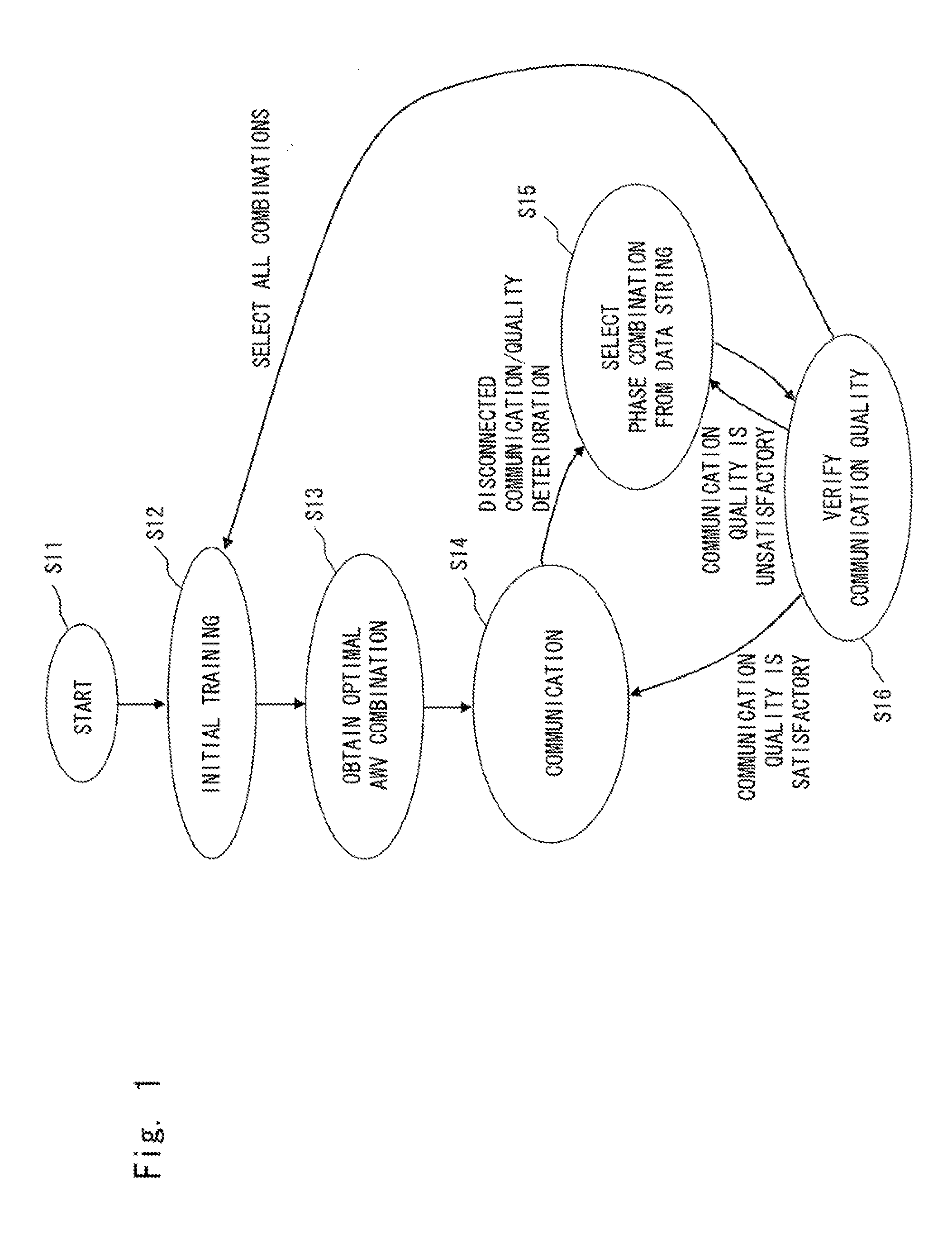
[0070]A first exemplary embodiment of the present invention is explained hereinafter with reference to a transition diagram shown in FIG. 1. It should be noted that a device configuration shown in FIG. 5, for example, can be used as the device configuration of the wireless communication system according to this exemplary embodiment.

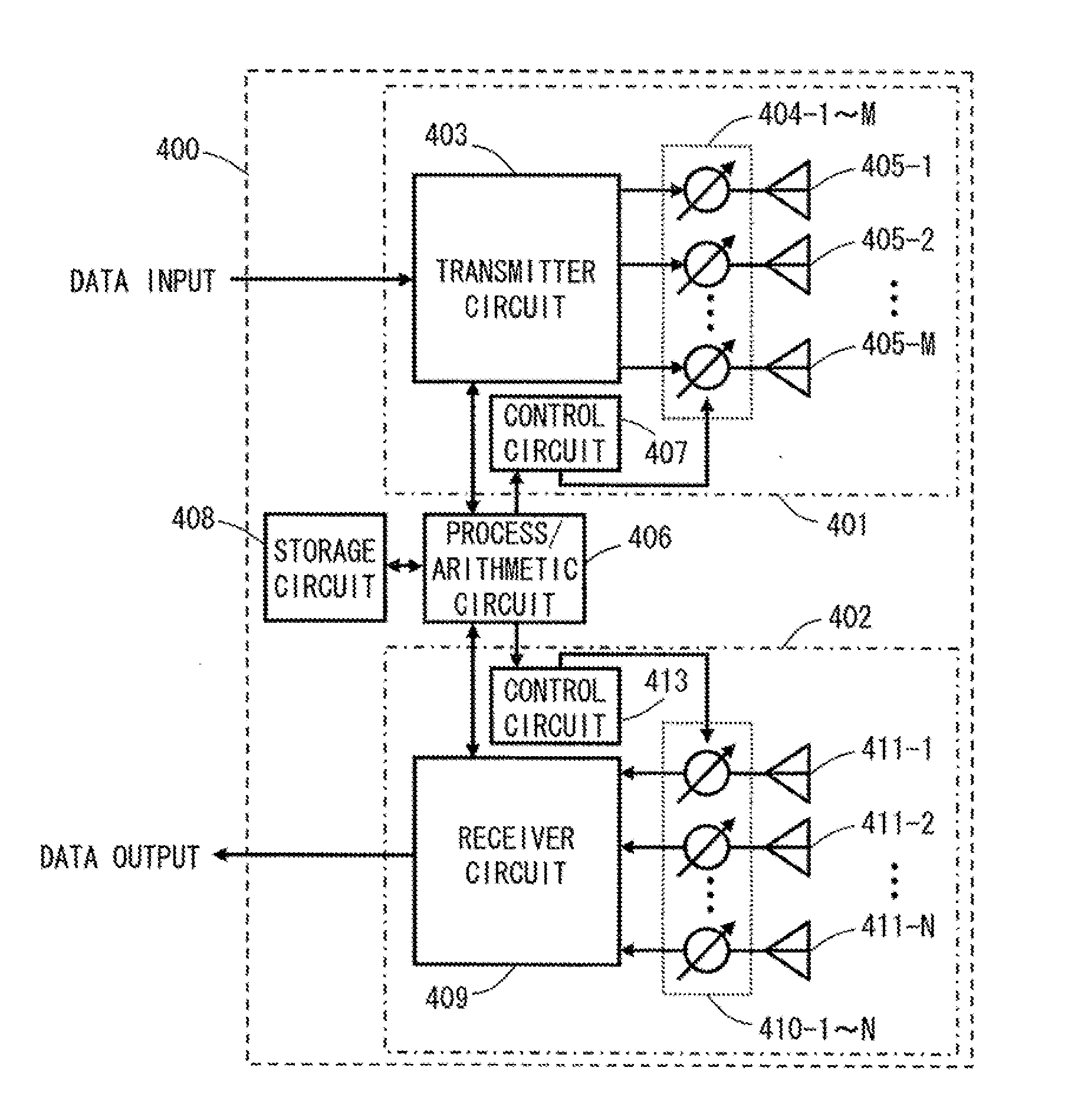
[0071]In a state S12 in FIG. 1, transceivers 400 and 500 perform an initial training to optimize AWV control circuits 404-1 to 404-M, 410-1 to 410N, 504-1 to 504K, and 510-1 to 510L provided therein. In S13, candidate AWV combinations are calculated by a process / arithmetic circuit 406 or 506 or by cooperation of these two circuits. The calculation method for candidate AWV combinations in S13 will be explained later. The obtained candidate AWV combinations are stored as a data string in both or either of the storage circuits 408 and 508.

[0072]In S14, one of the candidate AWV combinations obtained in S13 is selected, and communication is performed by using ...

second exemplary embodiment

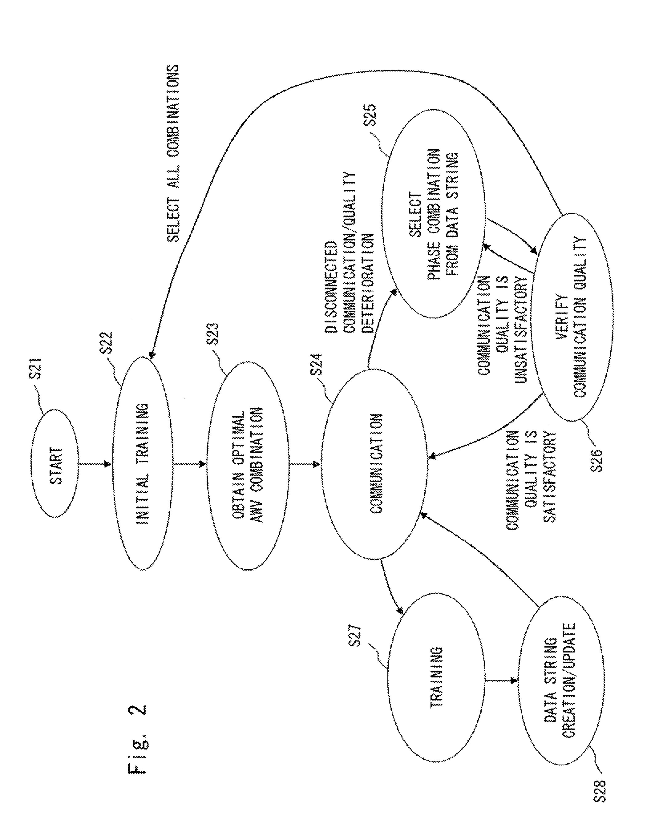
[0125]A second exemplary embodiment of the present invention is explained hereinafter with reference to a transition diagram shown in FIG. 2. It should be noted that a configuration similar to that shown in FIG. 5 can be used as the configuration of a wireless communication system in accordance with this exemplary embodiment. Each of states S21 to S26 and transition conditions therebetween in FIG. 2 are similar to S11 to S16 and their transition conditions shown in FIG. 1, which are described above with the first exemplary embodiment. Therefore, detailed explanation of S21 to S26 is omitted.

[0126]In S27 in FIG. 2, an additional second training is performed after transition from the state (S24) where the communication is continued. The second training may be periodically performed or may be performed during idle times in which there is no data to be transmitted / received.

[0127]In S28, the process / arithmetic circuit 406 and 506 calculate a plurality of candidate AWV combinations again....

fourth exemplary embodiment

[0132]A fourth exemplary embodiment is characterized in that the training and the acquirement / establishment of AWV combinations are performed at a low-rate (with a narrow band) and actual communication is performed at a relatively high-rate (with a wide band). The other operations may be performed by using the method in accordance with one of first to third exemplary embodiments.

[0133]In millimeter wave communication, since free space propagation losses are large, the received power is expected to be small. Therefore, if AWVs on the transmission side are set so as to generate an omni or quasi-omni pattern in the training, there is a possibility that a sufficient CNR (Carrier to Noise Ratio) is not achieved. Accordingly, it is expected that the use of the low-rate (narrow band) having better reception sensitivity provides advantageous effects such as making the training possible and improving the accuracy. It should be noted that the “use of low speed (narrow band)” means to narrow t...


PUM


Abstract

To suppress adverse effects caused by side lobes of an antenna array when an AWV to be used for communication is determined based on a transmission/reception result of a training signal. A first transceiver generates a fixed beam pattern and transmits a training signal. In that state, a second transceiver receives the training signal while scanning for the main beam direction, and thereby determines a plurality of direction of arrivals (DOAs). Next, the second transceiver receives the training signal in a state where the signal receptions from the plurality of DODs are restricted one by one (e.g., a null direction or a direction close to the null direction is fixed in the DOA), and calculates the change of the signal characteristics from that obtained in the first reception. The transceivers obtain and use at least one AWV having the main beam direction or a sub-beam direction close to the main beam pointing to one of the plurality of DOAs except for the DOA for which the change is lower than a predefined threshold.

Description

TECHNICAL FIELD[0001]The present invention relates to a system that performs wireless communication by adaptively controlling radio beams, and its control method.BACKGROUND ART[0002]In recent years, use of wireless devices using wideband millimeter waves (30 GHz to 300 GHz) has become increasingly widespread. The millimeter-wave radio technology has been expected to be used especially for high-rate wireless data communication in the order of gigabit such as wireless transmission of high-resolution images (for example, see Non-patent literatures 1, 2 and 3).[0003]However, millimeter waves having high frequencies have a high rectilinear propagation property, and therefore they pose a problem in cases where wireless transmission is to be implemented indoors. In addition to the high rectilinear propagation property, millimeter waves are significantly attenuated by a human body or a similar object. Therefore, if a person stands between the transmitter and the receiver in a room or a simi...

Claims


Application Information

Patent Timeline
Patent Type & Authority Applications(United States)
IPC IPC(8): H01Q3/00
CPCH01Q3/267H04W16/28H04B7/086H01Q3/30
Inventor HOSOYA, KENICHIMARUHASHI, KENICHIORIHASHI, NAOYUKI
Owner NEC CORP
Why Eureka
Try Eureka