[0007]An example of a gas turbine structure is disclosed in U.S. Pat. No. 5,259,183. The indentations in the outer ring creates a disturbance to the gas flow through the turbine, which reduces the efficiency of the engine.
[0008]It is desirable to increase the efficiency of the gas turbine by reducing the disturbance on the gas flow through the turbine. The strut according to an aspect of the invention includes an end portion which has a diverging shape so that an internal space is formed in the end portion for receiving at least part of an
engine mount. The invention, according to an aspect thereof, in particular relates to such struts at which engine mounting lugs are positioned.
[0010]In contrast, a strut according to an aspect of the invention has an end portion of the strut with a diverging shape so that an internal space is formed in the end portion for receiving at least part of an
engine mount. Due to the novel shape of the strut, the flow past the strut will be less disturbed. A particular reason for this is that the strut is free from fillet
radius in between respective ends of the strut. Small radii of the outer surface of a strut, which radii are present in a flow channel where the struts may be mounted, will generate a distortion of the flow. The distortion of the flow may in turn lead to that an engine where the flow channel is included becomes less efficient. In particular small radii in an area that are somewhat distant to the ends of the struts at a connection between the strut and an inner and outer ring respectively will lead to flow distortion. Preferably, the diverging shape of the strut defines a smooth transition in direction from a center portion of the strut towards the strut end.
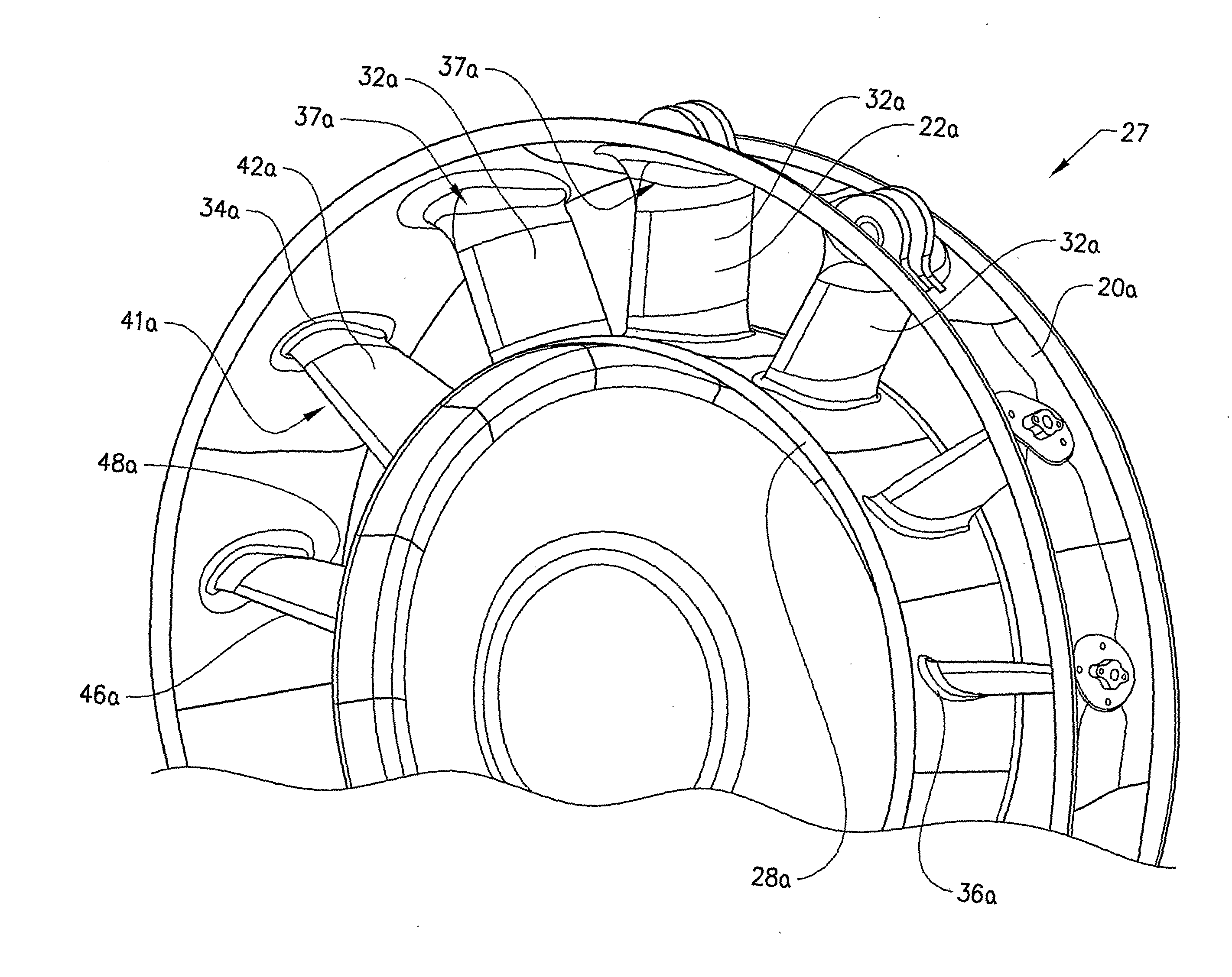
[0012]A strut may include first and second opposed strut faces being connected by a
front edge and a rear edge. At the end portion of the strut, the strut faces are diverging in at least at central parts of the first and second opposed end faces. The strut faces are diverging in the direction toward an outer ring. By diverging the strut faces, at least at central parts of the opposed end faces, in the direction toward the outer ring, a smooth transition between the end faces and the connection of the strut to the outer ring can be accomplished. With central parts intended a central part of the strut with respect to an extension of the strut in a direction from a
front edge to a rear edge of the strut. It may be sufficient to diverge the strut faces along this central part of the strut, which parts having a sufficient extension to make room for a recess adapted to accommodate component or a portion thereof such as typically an engine
mount lug. It is therefore not necessary to diverge the strut faces at the front and rear edges of the strut where respective strut faces are connected. By arranging the strut faces to be diverging in the central parts, the strut is constructed with a geometry allowing an internal space, such as a recess, being arranged to receive a component or a portion thereof. The internal space is arranged at the end portion of the strut. The strut geometry thus has a reduced
impact on the gas flow. This effect is achieved since the geometry of the strut according to an aspect of the invention to a lesser degree disturbs the gas flow through a flow channel where the strut may be mounted. For instance, the presence of a sharp fillet
radius at a location in the vicinity of an inner end of a recess, which prior art solutions suffer from, is avoided.
[0019]In another embodiment of the invention said edge portions changes from being concave to being convex within said smooth strut area. This enables the strut faces to more closely follow the form of the recess, while still fulfilling the requirement of keeping the smooth strut area void of any sharp structure. This enables reduction in consumption of material and may reduce the weight of the gas turbine structure. The curvature radius may have a minimum value in the smooth strut area at a location radially inside of said inner end of said recess. An inflection point at which said edge portions changes from being concave to being convex may be located within an inner end area extending from a location located D / 6 radially inside said inner end of said recess to a location D / 6 radially outside said inner end of said recess. The position of the inflection point at this location also enables the strut faces to closely follow the form of the recess. Furthermore a derivative of said curvature radius may be monotonously increasing outwardly in a radial direction in said smooth strut area up till said inflection point, at which the derivative will be decreasing. The curvature radius is thus decreased outwardly in the radial direction up to the location of the minimum value of the curvature from where the curvature radius increases up to the inflection point. After the inflection point, the curvature radius will be decreasing again. A second deflection point may be present in order to allow a smooth transition between the strut and the outer ring.
[0023]A joint between the strut and the ring may be positioned, in a radial direction, further from said inner ring than a bottom of said recess. By locating the joint between the strut and the outer ring as close to the radius of the outer ring as possible, that is a far from the inner ring as possible, the
impact of any fillet radius present will be reduced. If the joint is located in the smooth strut area, the condition for the curvature radius imposed on the smooth strut area should be fulfilled. In the event the joint is located radially outside of the smooth strut area, the joint between the strut and outer ring may fulfil the condition for the curvature radius imposed on the smooth strut area. The outer ring would then form a continuous
smooth surface at a sector including the location of the joint between the ring and the strut.

