Propellant Flow Actuated Piezoelectric Igniter for Combustion Engines
a piezoelectric igniter and propellant flow technology, which is applied in the direction of generator/motor, lighting and heating apparatus, transportation and packaging, etc., can solve the problem that none of these prior inventions have been practically successful in solving this problem, and achieve a strong and reliable spark response, and a better method of igniting the rocket propulsion system
- Summary
- Abstract
- Description
- Claims
- Application Information
AI Technical Summary
Benefits of technology
Problems solved by technology
Method used
Image
Examples
second embodiment
[0074]One disadvantage of the second embodiment, oscillating piezoelectric igniter, shown in FIGS. 6 through 11 is that it uses two piezoelectric crystals arranged in a roughly symmetrical manner. Operation of the two piezoelectric crystals in parallel might be undesirable.
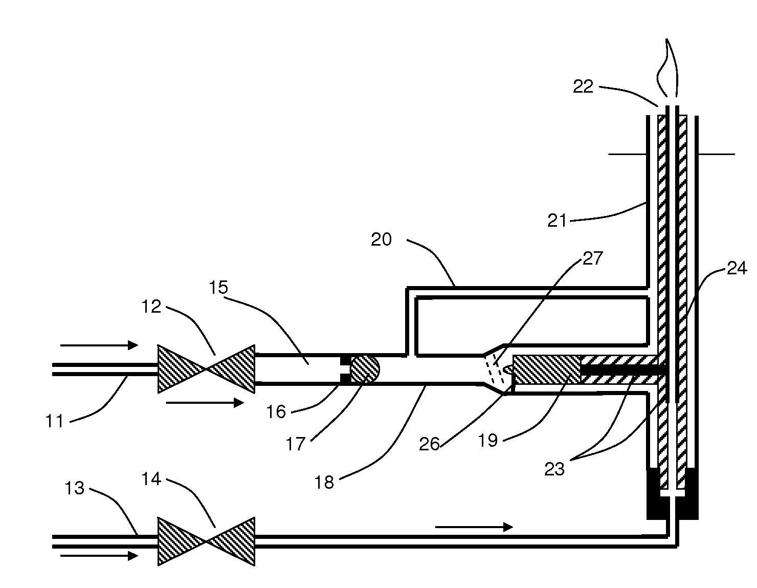
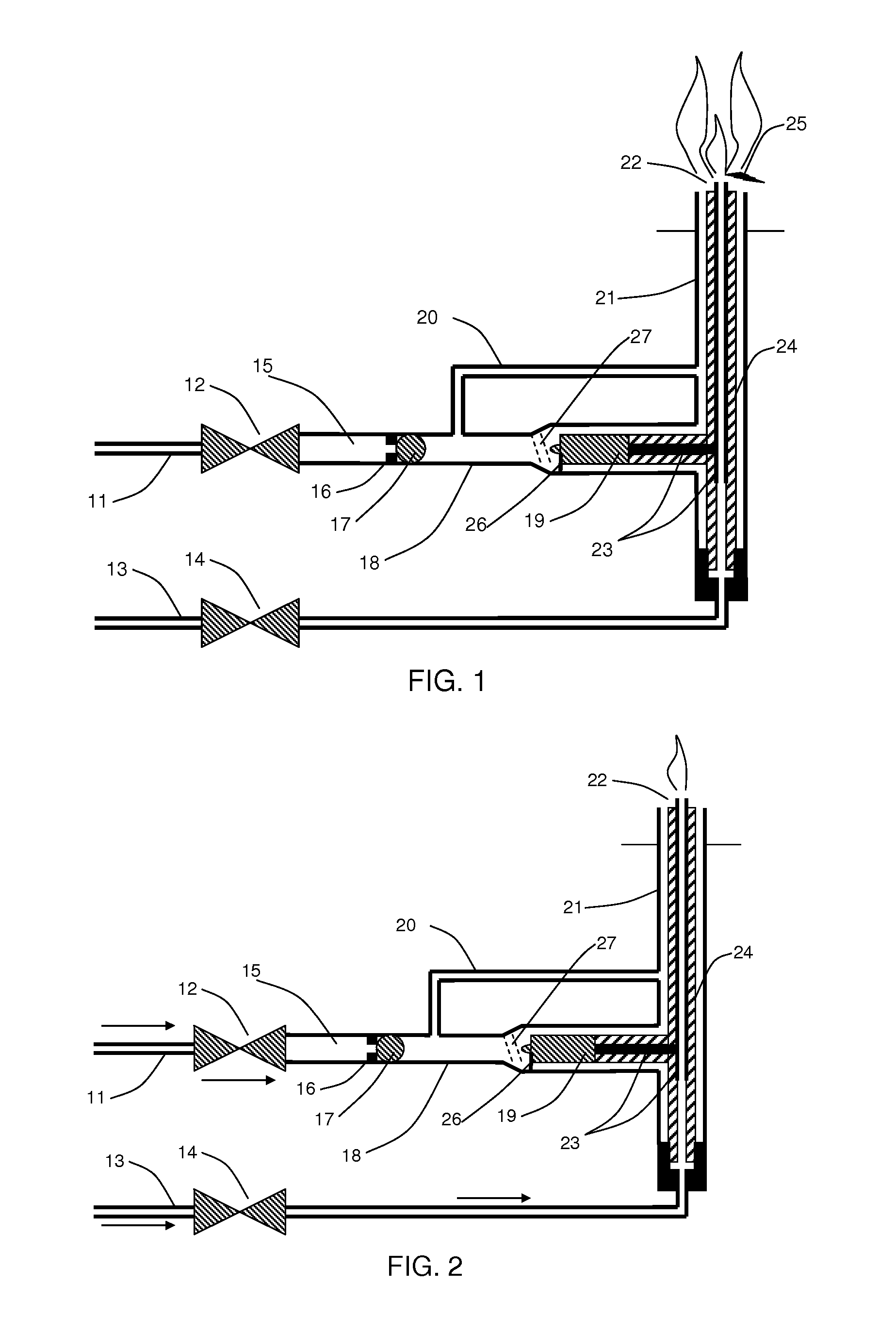
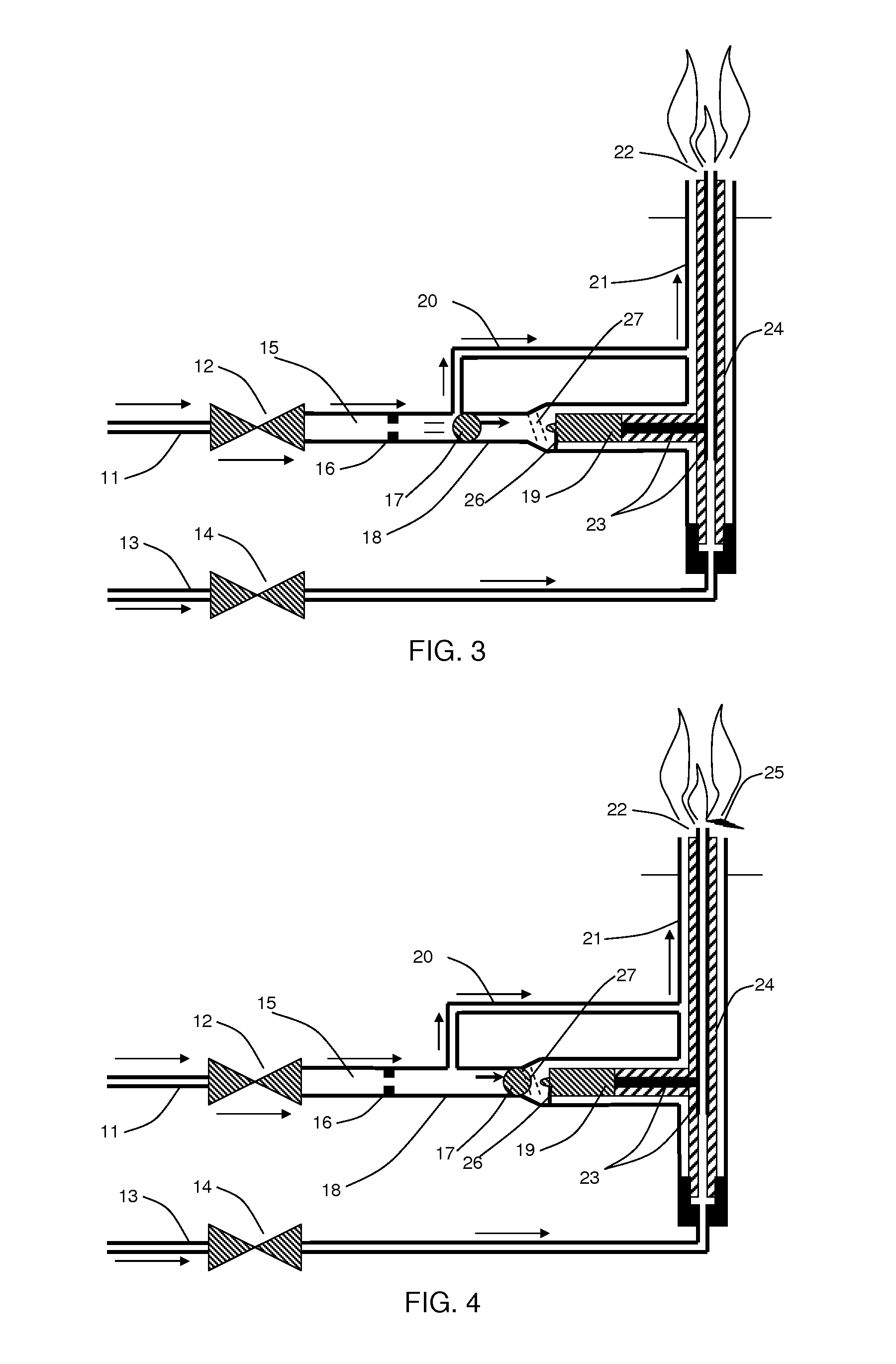
[0075]A third embodiment of the present invention provides an alternate oscillating piezoelectric igniter using one piezoelectric crystal resembling the first embodiment of the present invention in FIG. 1, while retaining the oscillating characteristics of the second embodiment of FIG. 6. An additional feature of the third embodiment is that it does not require magnets to maintain oscillation of the hammer ball, although one or more magnets may be employed to position the hammer ball prior to start.
[0076]The third embodiment, shown in FIG. 12, is accomplished by adding the following components to the first embodiment: isolated return gas chamber (53) surrounding the piezoelectric crystal (19), an isolated return c...
first embodiment
[0078]When the fuel inlet valve (12) is opened, gas flows into the upstream gas chamber (15), increasing pressure in the upstream gas chamber in a manner identical to that in the first embodiment, until hammer ball (17) is driven towards the piezoelectric crystal (19).
third embodiment
[0079]In the invention, the return anvil magnet (54) will retain the hammer ball (17) such that the return gas chamber (53) is sealed and will increase in pressure due to flow supplied through the return chamber gas supply path (52). When return gas chamber (53) pressure builds sufficiently, the hammer ball (17) will release from the return anvil magnet (54) to again become seated in the primary magnet (16).
[0080]Alternatively, with proper sizing of the primary and secondary charging orifices, and proper selection of the length of the guide tube and mass of the hammer ball, it is possible to cause the hammer ball to oscillate and repetitively impact the piezoelectric crystal without the need for magnets (16 and 54) and associated seals. The hammer ball is then operated continuously in a cycle to create reciprocating repeating sparks so long as needed.
[0081]This can be made to occur by sizing the secondary charging orifice (51) such that pressure in the return gas chamber (53) does n...
PUM
 Abstract
Description
Claims
Application Information
 - R&D
- Intellectual Property
- Life Sciences
- Materials
- Tech Scout
- Unparalleled Data Quality
- Higher Quality Content
- 60% Fewer Hallucinations
Browse by: Latest US Patents, China's latest patents, Technical Efficacy Thesaurus, Application Domain, Technology Topic, Popular Technical Reports.
© 2025 PatSnap. All rights reserved.Legal|Privacy policy|Modern Slavery Act Transparency Statement|Sitemap|About US| Contact US: help@patsnap.com


