Method for monitoring rotary shaft rotation speed fluctuation in machine tool, monitor apparatus, and machine tool

a technology of monitor apparatus and rotary shaft, which is applied in the direction of metal-working machine components, instruments, manufacturing tools, etc., can solve the problems of increasing and damage of motors, difficulty for unskilled operators to choose the parameters to be fluctuated, and limit of electric current, so as to suppress the chatter vibration

Active Publication Date: 2012-04-26
OKUMA CORP
View PDF0 Cites 22 Cited by
  • Summary
  • Abstract
  • Description
  • Claims
  • Application Information

AI Technical Summary

Benefits of technology

[0040]In the invention of the seventeenth aspect, in addition to the merits of any one of the fourteenth to sixteenth aspects, a current fluctuation value and a new fluctuation value can be readily recognized by the graph, and setting of the fluctuation values can be more readily conducted.
[0041]In the invention of the eighteenth aspect, either one of the amplitude and the period and either one of the rotary shaft torque of the rotary shaft and the power applied to the motor for rotating the rotary shaft are used for the parameter, and a parameter-setting unit is provided for setting the par

Problems solved by technology

However, the methods described in Japanese Patent Laid-Open No. 49-105277 and Japanese Utility Model Publication No. 61-3522 had the problem that setting of two parameters, namely, the fluctuation amplitude and the fluctuation period (hereinafter referred to as the “fluctuation values” when differentiation between these parameters are not required) had been necessary to fluctuate the rotation speed, and it had been difficult for an unskilled operator to choose the parameters to be fluctuated.
An upper limit is present for the electric current applied to the motor

Method used


Image

  • Method for monitoring rotary shaft rotation speed fluctuation in machine tool, monitor apparatus, and machine tool
  • Method for monitoring rotary shaft rotation speed fluctuation in machine tool, monitor apparatus, and machine tool
  • Method for monitoring rotary shaft rotation speed fluctuation in machine tool, monitor apparatus, and machine tool

Examples


embodiment 1

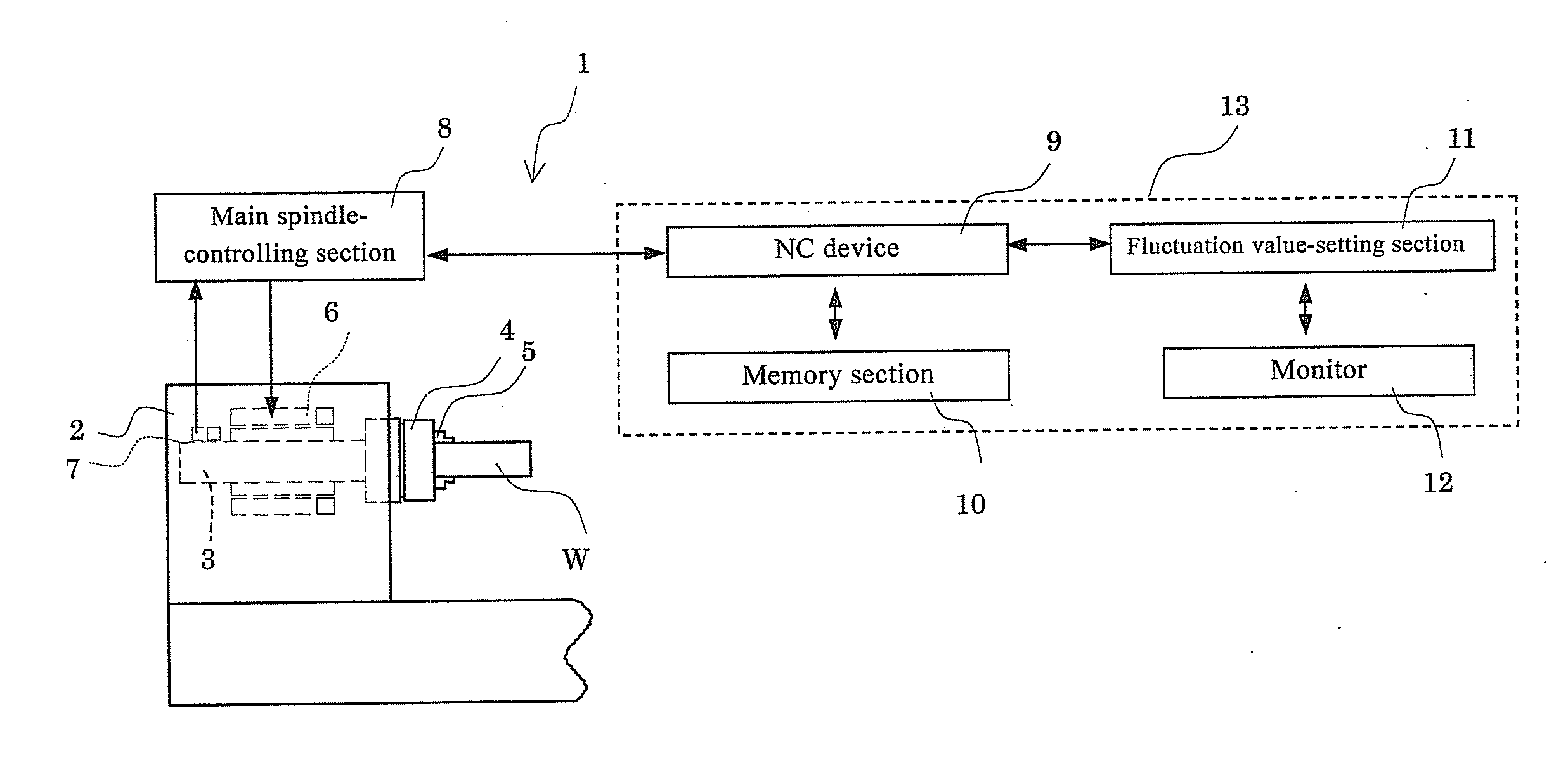
[0059]FIG. 1 is a schematic view of an NC lathe 1 which is an embodiment of the machine tool. In the NC lathe 1, a main spindle 3 (rotary shaft) is rotatably supported on a headstock 2, and the main spindle 3 grips a workpiece W by a chuck 4 and claws 5. The headstock 2 accommodates a motor 6 which is driven to rotate the main spindle 3 and an encoder 7 secured to the headstock 2 and configured to detect the rotation speed of the main spindle 3.

[0060]The motor 6 and the encoder 7 are connected to a main spindle control section 8, and an NC device 9 gives instructions on the rotation speed to the main spindle control section 8. The main spindle control section 8 continuously monitors the rotation speed of the main spindle 3 detected by the encoder 7, and adjusts the power applied to the motor 6 so that the main spindle 3 rotates at the rotation speed instructed by the NC device 9.

[0061]The NC device 9 is connected to a memory section 10 which stores processing and other programs, and...

embodiment 2

[0075]Next, another embodiment of the present invention is described. General constitution of the NC lathe 1 including the monitor apparatus 13 and the monitoring procedure are common to those of the Embodiment 1 despite difference in the display of the monitor in the fluctuation value-setting section 11. Accordingly, the monitor display is mainly described while omitting the repetitive descriptions.

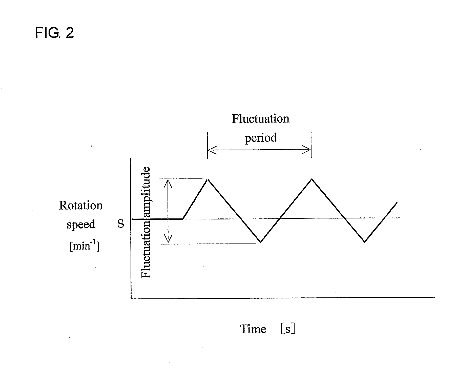
[0076]In the embodiment 1 as described above, the fluctuation period was used for the value fluctuated. However, monitoring and fluctuation of the rotation speed of the main spindle 3 can also be accomplished by using angular acceleration for the fluctuation of the rotation speed of the main spindle 3. Angular acceleration represents change in the rotation speed per time, and the relation of the rotation speed S, the fluctuation period R, and the fluctuation amplitude Q of the main spindle 3 is as shown below in the equation (3). As explained for FIG. 5 that the effect of the chatter vib...

embodiment 3

[0091]In this embodiment 3, constitution of the NC lathe 1 is the same as that of the embodiments 1 and 2. The monitor 12 constitutes the display unit, and the fluctuation value-setting section 11 constitutes the fluctuation value setting unit. The rotation speed of the main spindle 3 can be fluctuated at the instructed fluctuation amplitude and fluctuation period as shown in FIG. 9 by entering the rotation speed and its fluctuation amplitude and fluctuation period of the main spindle 3 from the monitor 12 having an input unit to the fluctuation value-setting section 11, and controlling the main spindle 3 via the NC device 9 (the rotation speed-fluctuation unit) and the spindle controlling section 8.

[0092]When the fluctuation amplitude and fluctuation period are entered in the fluctuation value-setting section 11, the monitor 12 displays a graph 20 wherein the fluctuation amplitude (y-axis) is shown in relation to the fluctuation period (x-axis) as shown in FIG. 10. This graph also ...


PUM


Abstract

In suppressing chatter vibration of a rotary shaft in a machine tool by fluctuating rotation speed of the rotary shaft, easy setting of a fluctuation parameter is realized. In a monitor apparatus of the machine tool, a graph showing a fluctuation amplitude of the rotation speed is displayed. On this graph, a current fluctuation position (first point) is indicated by a black circle marker, and also, a power limit line L of a motor fluctuation period is depicted based on a predetermined equation. In an area not exceeding the power limit line L, a new fluctuation position (second point) having a larger fluctuation amplitude and a shorter fluctuation period than the current fluctuation position is calculated and indicated with an arrow A guiding this new point from the current fluctuation position.

Description

BACKGROUND OF THE INVENTION[0001]This application claims the benefit of Japanese Patent Application Numbers 2010-235720, 2010-237704 and 2010-284815 filed on Oct. 20, 2010, Oct. 22, 2010 and Dec. 21, 2010 respectively, the entirety of which is incorporated by reference.TECHNICAL FIELD[0002]This invention relates to a method for monitoring rotation speed fluctuation of a rotary shaft of a machine tool having the rotary shaft driven by a motor after mounting a tool or a workpiece thereon, wherein rotation speed of the rotary shaft is continuously fluctuated at an arbitrary pattern. This invention also relates to a monitor apparatus and a machine tool.BACKGROUND ART[0003]A phenomenon called “chatter vibration” may occur when cutting is conducted by using a machine tool having a rotary shaft driven by a motor after mounting a tool or a workpiece thereon, and rigidity of the tool or the workpiece is insufficient. The chatter vibration is associated with the problems of tool chipping and ...

Claims


Application Information

Patent Timeline
IPC IPC(8): B23Q5/00G06F15/00
CPCB23Q17/12B23Q17/10
Inventor YOSHINO, KIYOSHIISHII, HAJIMUNISHIMURA, KOHEI
Owner OKUMA CORP
Why Eureka
Try Eureka