Synchronous regulation for LED string driver

a technology of led string driver and synchronous regulation, which is applied in the direction of electroluminescent light source, lighting apparatus, light source, etc., can solve the problems of not being suitable for use with led strings, increasing cost and/or wasted energy, and requiring a power source for each led string is quite costly, so as to prevent large current swings and eliminate tail currents.

Inactive Publication Date: 2012-04-26
POLARIS POWERLED TECH LLC
View PDF7 Cites 23 Cited by
  • Summary
  • Abstract
  • Description
  • Claims
  • Application Information

AI Technical Summary

Benefits of technology

[0012]Accordingly, it is a principal object of the present invention to overcome at least some of the disadvantages of the prior art. This is provided in certain embodiments by an arrangement comprising at least one LED string connected in series with an electronically controlled switch, the at least one LED string receiving power from a power transformer secondary winding, the primary winding of the transformer arranged to receive power from a switching bridge. Preferably the switching bridge receives power from a PFC stage conne

Problems solved by technology

In one embodiment a power source is supplied for each LED string, and the voltage of the power source is controlled in a closed loop to ensure that the voltage output of the power source is consonant with the voltage drop of the LED string, however the requirement for a power source for each LED string is quite costly.
Either of these solutions adds to cost and/or wasted energy.
The balancer requires an alternating current input in order to avoid DC saturation of the transformers, and is thus not suitable for use with LED strings, which operate only

Method used


Image

  • Synchronous regulation for LED string driver
  • Synchronous regulation for LED string driver
  • Synchronous regulation for LED string driver

Examples


Embodiment Construction

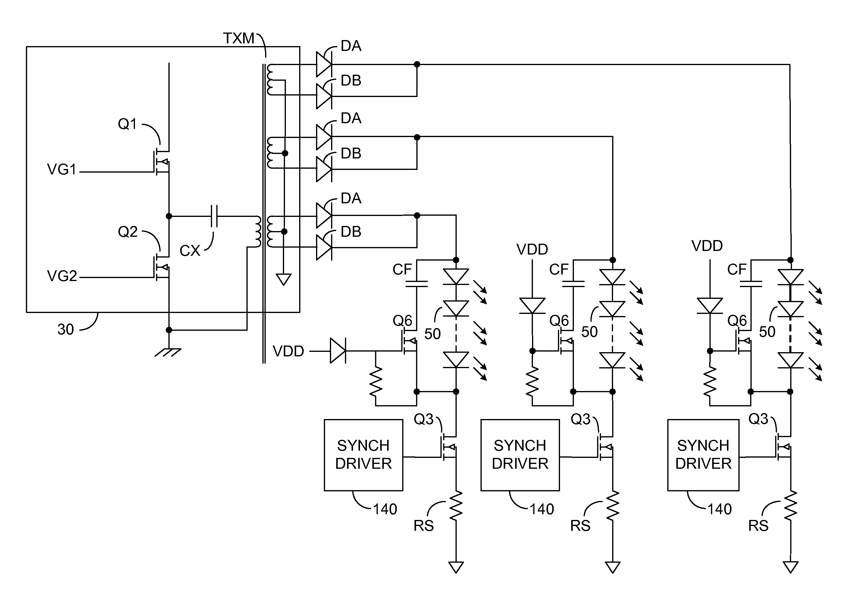
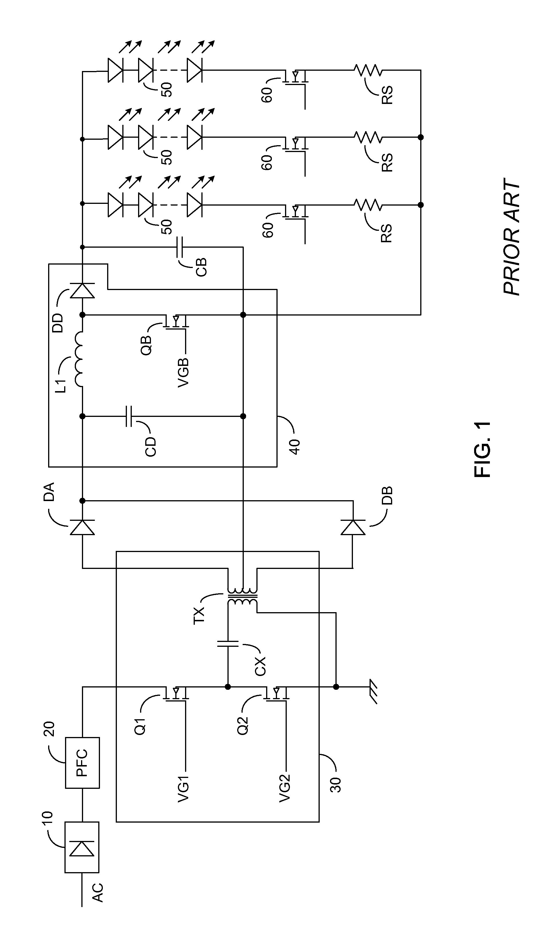
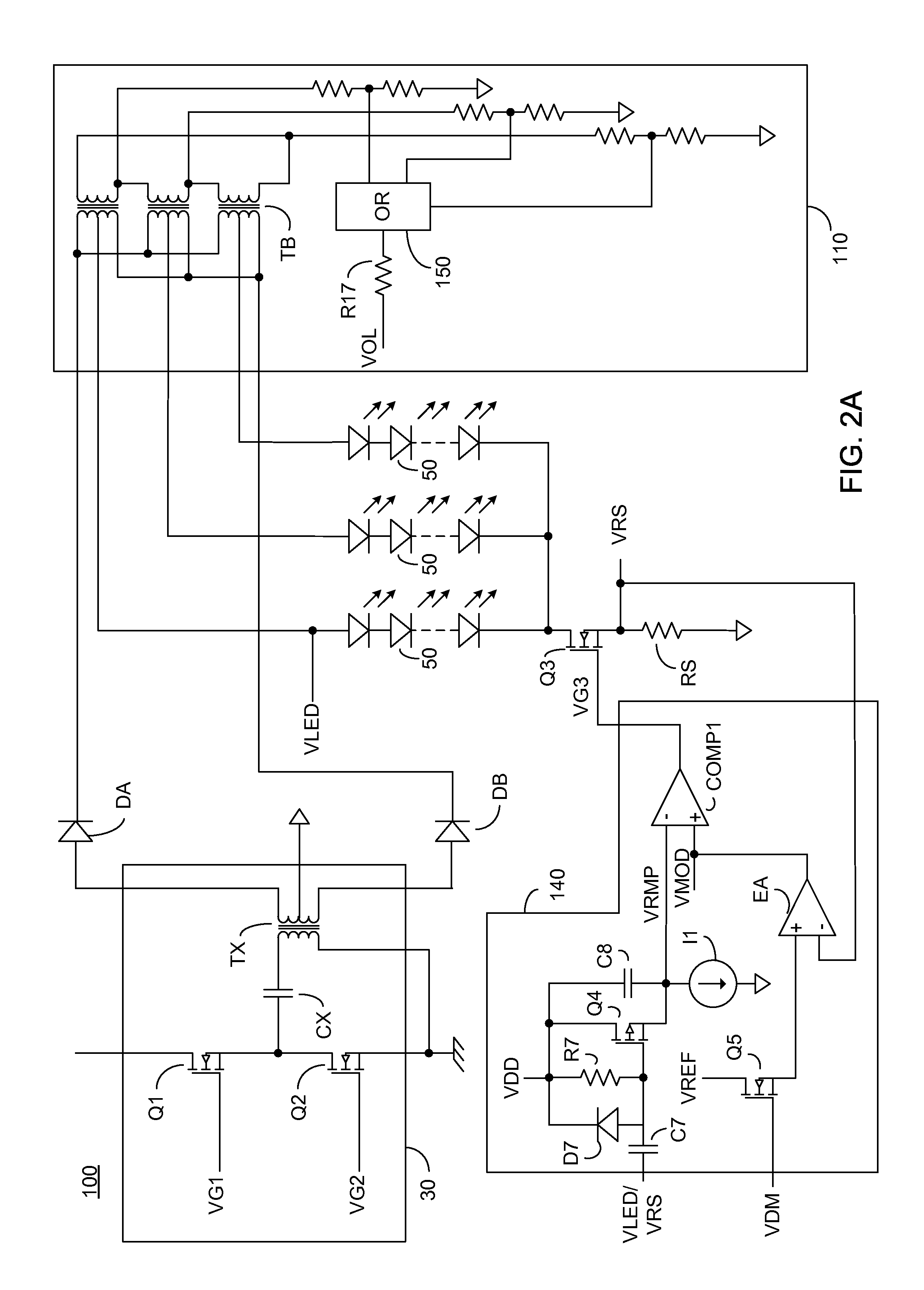
[0026]Before explaining at least one embodiment of the invention in detail, it is to be understood that the invention is not limited in its application to the details of construction and the arrangement of the components set forth in the following description or illustrated in the drawings. The invention is applicable to other embodiments or of being practiced or carried out in various ways. Also, it is to be understood that the phraseology and terminology employed herein is for the purpose of description and should not be regarded as limiting. The term winding is particularly meant to mean a winding of electrically conducting wire forming an inductor. The winding may form a stand alone inductor, or be magnetically coupled to another winding forming a transformer. Certain embodiments are described herein in relation to LED strings, however this is not meant to be limiting but is rather a particular example of an LED based luminaire. A single high powered LED or other LED based lumin...


PUM


Abstract

A light emitting diode (LED) based luminaire driving arrangement constituted of: a switched driver; a plurality of LED based luminaires arranged to receive power from the switched driver; at least one electronically controlled switch in series with at least one of the plurality of LED based luminaires and arranged to alternatively pass current through the at least one LED based luminaire when closed and prevent the flow of current through the at least one LED based luminaire when opened; and at least one synchronous driver in communication with the at least one electronically controlled switch, the at least one synchronous driver arranged to close the at least one electronically controlled switch only when the switched driver is actively supplying power.

Description

CROSS-REFERENCE TO RELATED APPLICATION[0001]This application claims priority from U.S. Provisional Patent Application Ser. No. 61 / 406,136 filed Oct. 24, 2010, entitled “Synchronous Regulation for LED String Driver”, the entire contents of which is incorporated herein by reference.BACKGROUND OF THE INVENTION[0002]The present invention relates to the field of solid state lighting, and in particular to an arrangement of one or more LED strings switched synchronously with input switches of a single stage power supply.[0003]Light emitting diodes (LEDs) and in particular high intensity and medium intensity LED strings are rapidly coming into wide use for lighting applications. LEDs with an overall high luminance are useful in a number of applications including backlighting for liquid crystal display (LCD) based monitors and televisions, collectively hereinafter referred to as a matrix display, as well as for general lighting applications.[0004]In a large LCD matrix display, and in large s...

Claims


Application Information

Patent Timeline
IPC IPC(8): H05B37/02H05B44/00
CPCH05B33/0827H05B33/0815H05B45/46H05B45/3725H05B45/38H05B45/37
Inventor JIN, XIAOPING
Owner POLARIS POWERLED TECH LLC
Why Eureka
Try Eureka