
Tracking lane marker position through use of information-transmiting device

Inactive Publication Date: 2012-04-26
BOGATINE OLEG
View PDF5 Cites 34 Cited by
  • Summary
  • Abstract
  • Description
  • Claims
  • Application Information

AI Technical Summary

Benefits of technology

[0012]The purpose of the present invention is to provide a lane position sensor system, which can accurately detect a lane marker line no matter how difficult lightening conditions are and unambiguously determine what kind of line it is.
[0018]RFID tags that have been installed on a road near different marker lines may transmit different digital signal by which the system will detect which particular line a vehicle is approaching to or crossing it over. This feature is really advantageous because it allows from one hand to completely avoiding complex and expensive image detecting and processing for image based system, and from other hand does not depend upon hard lightening conditions which are the most frequent cause of fails of the imaging systems.

Problems solved by technology

One of the reasons of automobile road accidents which practically every driver has experienced while driving for a long time is the feeling of drowsiness or looking away of the direction of travel or any other way of loosing control of the operated vehicle, which makes driver inattentive.
It may cause the vehicle to swerve and unintentionally change the lane on a road.
This becomes a cause of thousands of accidents every year.
The main light-sensitive cell approach disadvantage that it is inaccurate, either insensitive in case of low lighting or too sensitive, or may be triggered by radiation of all kinds such as from passing cars, or radiations from light pavement and the like.
The main problem for this category of the lane tracking systems is a poor lane imaging under harsh lighting conditions, such as nighttime driving where oncoming headlights can saturate the imaging system making it impossible to detect lane markers illuminated by the vehicle headlights.
Another example is bright sunlight where glare off the roadway can saturate the image so the roadway lane markers cannot be accurately detected.
Though image processing solutions become more and more complex and costly they in principal may not be successful in all of the lighting and road conditions which will be experienced in real world applications.
Another problem of the prior arts solution is that even if they detect a lane marker accurately the only limited information may be provided.
It should be noted that such universal information like global positioning coordinates themselves, providing by GPS, is still useless for our purpose as it does not provide information of the position of the vehicle with respect to the road marking.

Method used


Image

  • Tracking lane marker position through use of information-transmiting device
  • Tracking lane marker position through use of information-transmiting device
  • Tracking lane marker position through use of information-transmiting device

Examples


Embodiment Construction

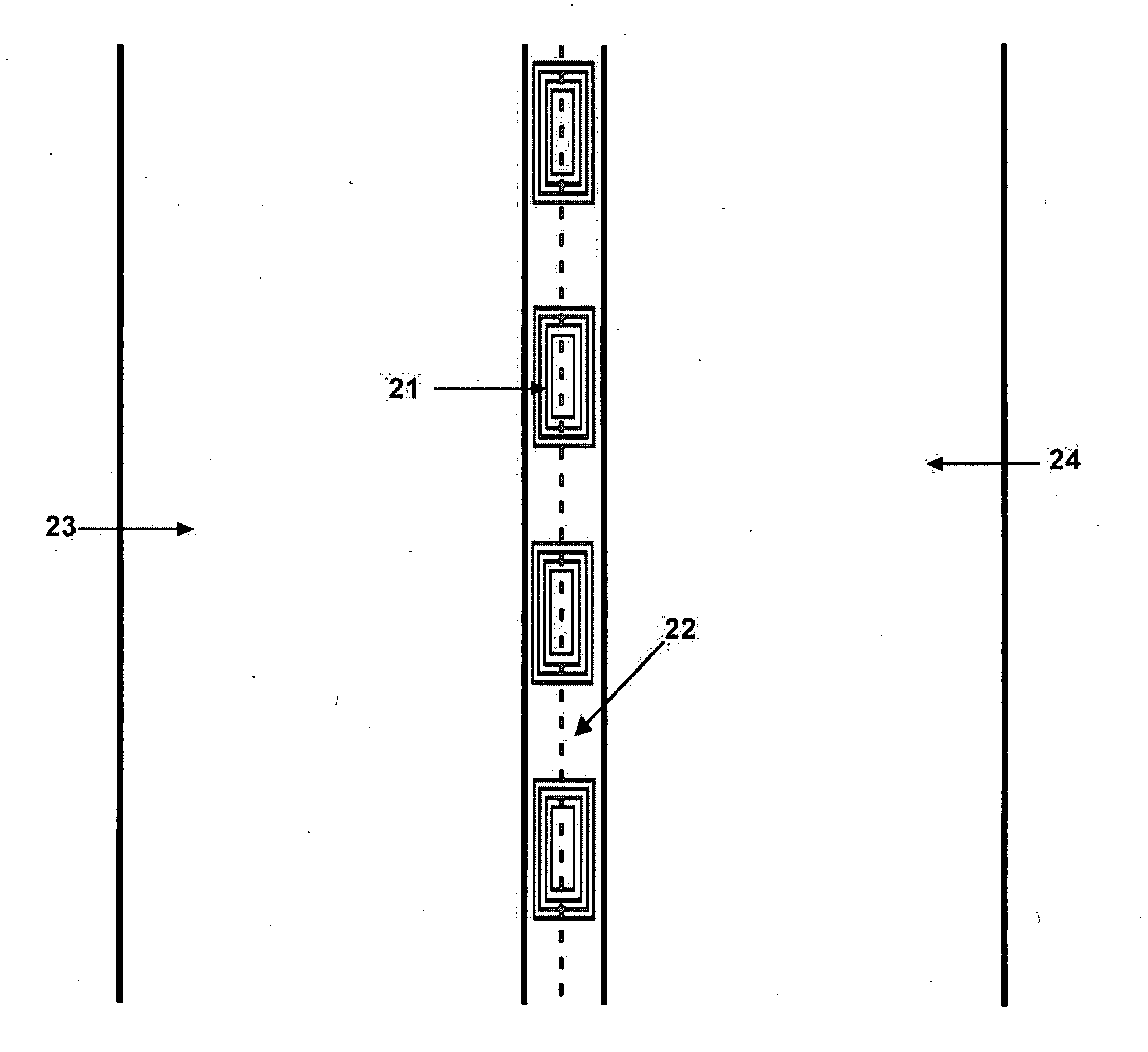
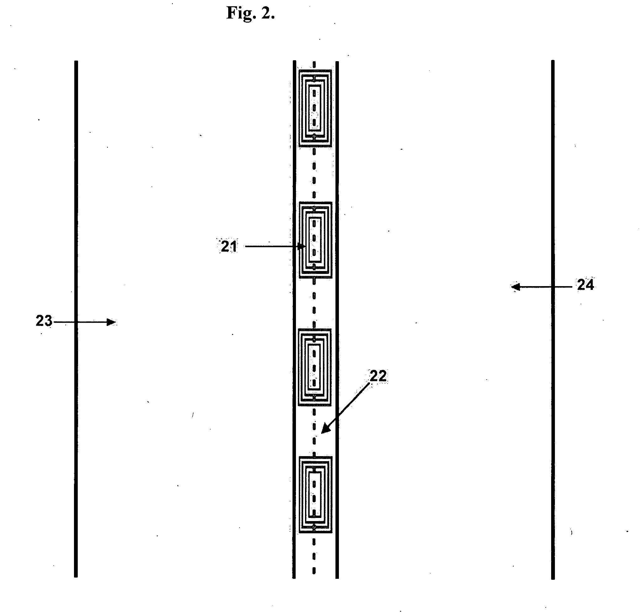
[0027]Embodiments of the present invention enable detection of the position of vehicles using information-transmitting devices installed on a road in certain order with respect to the road marking. One example of this kind of devices is RFID tags.

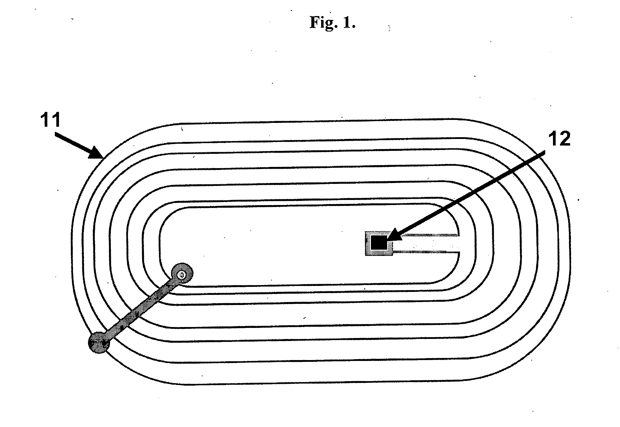
[0028]The tags may be placed in proximity or just directly on the marking line which they suppose to detect when the vehicle is either approaching or crossing such a line. Such a tag may be installed individually in which case it has been presented most often as a polymer label-like base with a tag on it. The simple way to attach this label to the road surface is just to spray an adhesive to one side of the label and apply the label with an adhesive side to the road surface.

[0029]As another alternative the RFID tags may be attached to the tape with an adhesive surface and applied to the road by rolling out the tape roll down the road. There is a variety of applicators of all kinds in industry which are performing this simple operation. The ...


PUM


Abstract

Detecting position of the vehicle with respect to the lane marker lines through use of information-transmitting devices has been proposed. At least one row of information-transmitting wireless devices is provided for a lane marker line, wherein each of the devices is adapted for transmitting information to a reader usable for detecting the position of the vehicle as it comes in close enough proximity to the wireless device. Each of the devices transmits a digital signal to the reader installed on the body of the vehicle, which contain information of the line styles (dashed, solid etc.), line colors (white, yellow or blue) and locations with respect to the road. The information-transmitting devices may be placed just on the road surface, at some depth of the road surface, on light reflectors, guardrails, traffic cones, or any other devices installed on a road for traffic control or for any other purposes. The information-transmitting devices may be positioned just on or on a side of the marker lines or on the center or in proximity of the center of the traffic lane. The method proposed allows detection of the lane marker line no matter how difficult lightening conditions are and unambiguously determine the nature of the line detected.

Description

[0001]References Cited3,201,750August 1962Morin340 / 9045,245,422September 1993Borcherts et al.358 / 1035,351,044September 1994Mathur et al.340 / 9015,835,028November 1998Bender et al.340 / 4366,930,593September 2005Crawshaw340 / 435BACKGROUND OF THE INVENTION[0002]The present invention relates to vehicle position tracking sensor and alarm system to signal driver when vehicle is changing or close to changing the road lane.[0003]One of the reasons of automobile road accidents which practically every driver has experienced while driving for a long time is the feeling of drowsiness or looking away of the direction of travel or any other way of loosing control of the operated vehicle, which makes driver inattentive. It may cause the vehicle to swerve and unintentionally change the lane on a road. This becomes a cause of thousands of accidents every year. The systems, which provide an alarm to alert the driver and other participants of the traffic to avoid such a dangerous situation, are known in ...

Claims


Application Information

Patent Timeline
IPC IPC(8): B60Q1/00
CPCB60W30/12B60W2050/143G08G1/167G05D2201/0213G08G1/164G05D1/0261
Inventor BOGATINE, OLEG
Owner BOGATINE OLEG
Features
  • Generate Ideas
  • Intellectual Property
  • Life Sciences
  • Materials
  • Tech Scout
  • Unparalleled Data Quality
  • Higher Quality Content
  • 60% Fewer Hallucinations
Learn More