Ultrasonic detection device

Active Publication Date: 2012-04-26
MITSUBISHI ELECTRIC CORP
View PDF5 Cites 8 Cited by
  • Summary
  • Abstract
  • Description
  • Claims
  • Application Information

AI Technical Summary

Benefits of technology

[0008]Because in accordance with the present invention, the discriminating processing unit approximates the shape of each signal which is the reflection signal or a noise as an isosceles triangle and computes the pulse time width equal to the length of the base of the above-mentioned approximating isosceles triangle, and discriminates between the reflection signal and the noise

Problems solved by technology

However, according to the technology disclosed by above-mentioned patent reference 1, because the waveform shaping is performed by using a fixed threshold, in the case in which neither the full-wave-rectified reflection signal nor a noise has a rectangular waveform, e.g., in the case in which the full-wave-rectified reflection signal and a noise are triangular-shaped pulses, the measurement values of the pulse time widths also change as their amplitudes change, and therefore the noise discrimination cannot

Method used


Image

  • Ultrasonic detection device
  • Ultrasonic detection device
  • Ultrasonic detection device

Examples


Example

Embodiment 1

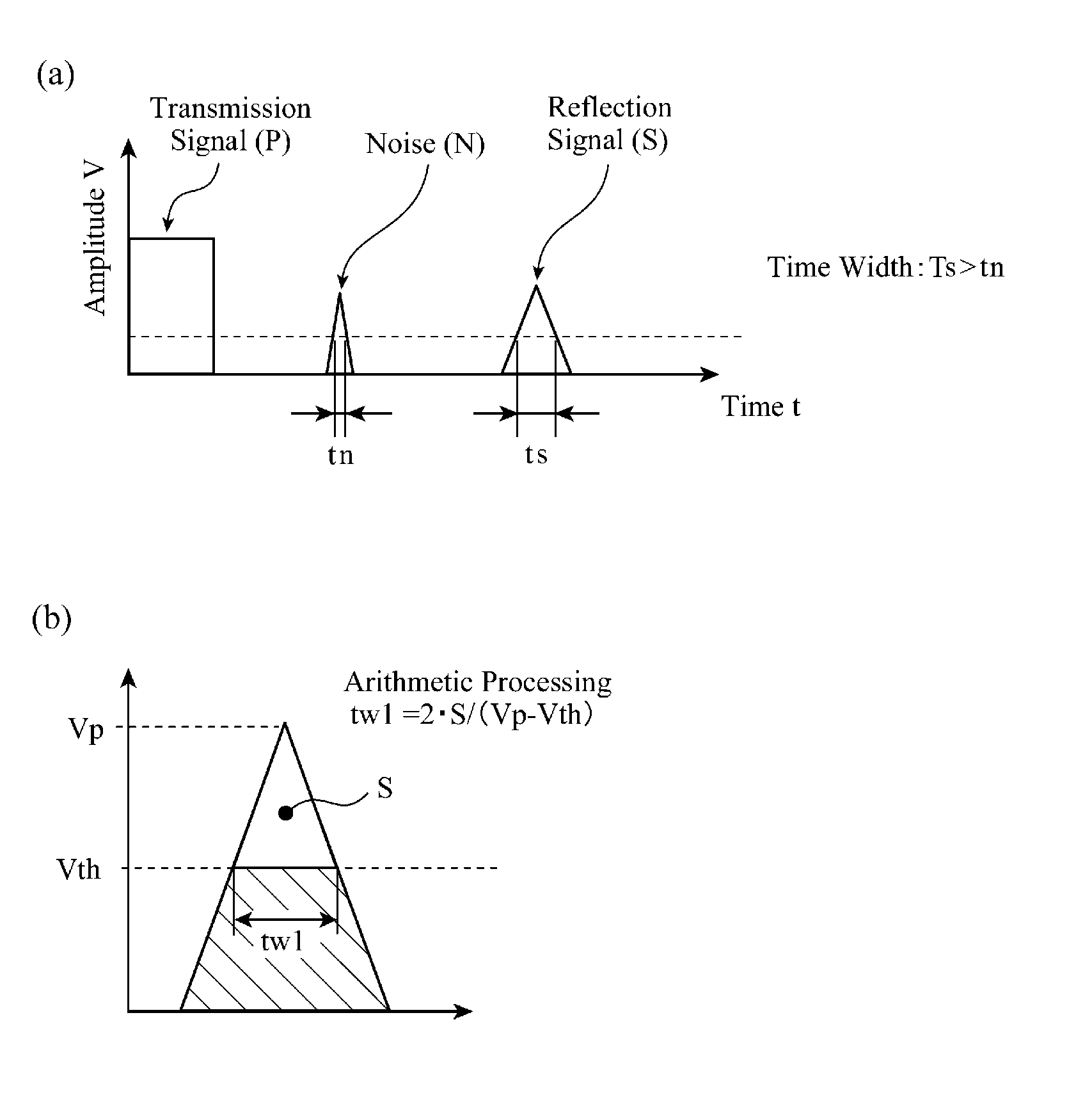
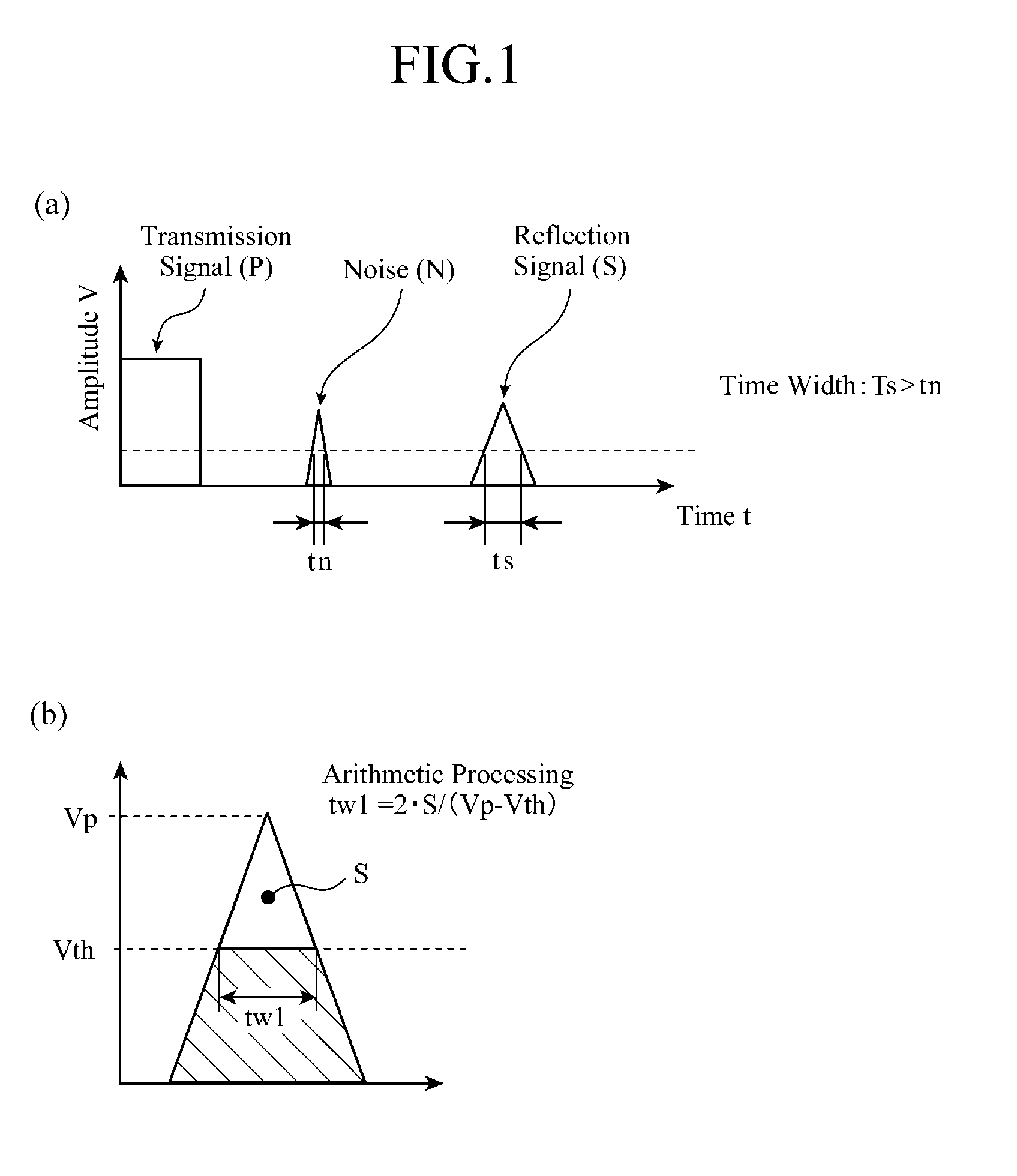
[0019]FIG. 1 is a view showing the principle behind noise discrimination carried out by an ultrasonic detection device in accordance with this Embodiment 1. In FIG. 1(a), the waveforms of a transmission pulse transmitted by and a reception pulse received by a pulser / receiver disposed in the ultrasonic detection device in accordance with this Embodiment 1. In FIG. 1(b), an area S, a maximum amplitude Vp, and an amplitude threshold Vth which are parameters used when computing a pulse time width tw1 are shown in the waveform of a signal which is a reflected wave signal or a noise.

[0020]For example, the ultrasonic detection device in accordance with this Embodiment 1, which can be used as a corner sensor of a vehicle, transmits an ultrasonic pulse toward an object from the pulser thereof, and receives a reflection signal from the object by using the receiver thereof. It is known that a noise component including an electromagnetism noise, a noise caused by a whizzing sound, a...

Example

Embodiment 2

[0036]FIG. 3 is a view showing the principle behind noise discrimination carried out by an ultrasonic detection device in accordance with this Embodiment 2, and FIG. 4 is a block diagram showing the structure of the ultrasonic detection device in accordance with this Embodiment 2.

[0037]As can be seen from FIG. 3, the ultrasonic detection device in accordance with this embodiment differs from that in accordance with Embodiment 1 shown in FIG. 1(b) in that after approximating the waveform of a reflected wave S (a noise n) as an isosceles triangle, like that of Embodiment 1, further determines a similar isosceles triangle from a similarity expression of the isosceles triangle, and determines the length of the base of the similar isosceles triangle, i.e., the pulse time width tw2 of each of the reflection signal and the noise n according to the following computing equation (2). A noise discriminating process of discriminating between the reflected wave S and the noise n by d...

Example

Embodiment 3

[0040]FIG. 5 is a view showing the principle behind noise discrimination carried out by an ultrasonic detection device in accordance with this Embodiment 3, and FIG. 6 is a block diagram showing the structure of the ultrasonic detection device in accordance with this Embodiment 3.

[0041]Reflection signals S1 to S3 which are received at predetermined times (En0, En1, and En2) in synchronization with ultrasonic pulses transmitted by a pulser / receiver 12 in the ultrasonic detection device in accordance with this Embodiment 3 are shown in time sequence in FIGS. 5(a) to 5(c), respectively. FIG. 5(d) shows a signal component St which is acquired by combining (adding up) the reflection signals S1 to S3 respectively received at the times En0, En1, and En2.

In FIG. 5(d), tw1i shows the pulse time width of the reflection signal St which is acquired by combining (adding up) the reflection signals S1 to S3.

[0042]In this embodiment, the ultrasonic detection device performs a noise disc...


PUM


Abstract

An ultrasonic detection device is constructed in such a way as to include a discriminating processing unit (a time width detecting part 13 and a pulse width discrimination part 14) for approximating the shape of each signal which is a reflection signal which is reflected from an object as a result of transmitting a ultrasonic pulse toward the object, or a noise as an isosceles triangle and computing a pulse time width equal to the length of the base of the approximating isosceles triangle, and for discriminating between the reflection signal and the noise signal by determining whether the computed pulse time width exceeds a predetermined pulse width discrimination threshold. Therefore, the ultrasonic detection device can determine the pulse time width with stability, and carry out the discriminating process with a high degree of reliability.

Description

FIELD OF THE INVENTION[0001]The present invention relates to an ultrasonic detection device which transmits an ultrasonic pulse toward an object from a pulser, and discriminates a noise mixed into a reflection signal received by a receiver from the reflection signal by using their pulse time widths.BACKGROUND OF THE INVENTION[0002]An ultrasonic detection device as mentioned above is disclosed by patent reference 1, for example. The ultrasonic detection device disclosed in patent reference 1 measures a pulse time width and stores this pulse time width temporarily by amplifying a reflection signal into which a noise is mixed, and, after that, shaping the waveform of the reflection signal by counting a clock by using the reflection signal shaped in waveform as a gate. Then, the ultrasonic detection device measures pulse time widths sequentially by performing the same process, and, when the pulse time width of each of the immediately-preceding and next reflection signals is equal to or ...

Claims


Application Information

Patent Timeline
IPC IPC(8): G01S7/527
CPCG01S7/527
Inventor INOUE, SATORUSUZUKI, RYOTAROUARAKI, KUNIHIKO
Owner MITSUBISHI ELECTRIC CORP
Why Eureka
Try Eureka