
Method to provide electrical insulation between conductive plates of a hydrogen fuel cell

a technology of hydrogen fuel cell and conductive plate, which is applied in the field of fuel cell, can solve the problems of resin frame and adhesively bonded fuel cell plates, plate-to-plate contact under compression, undetectable time-consuming and cost prohibitive, etc., and achieve the effect of reducing the deformation of fuel cell plates and minimizing trimming

Inactive Publication Date: 2012-04-26
GM GLOBAL TECH OPERATIONS LLC
View PDF2 Cites 0 Cited by
  • Summary
  • Abstract
  • Description
  • Claims
  • Application Information

AI Technical Summary

Benefits of technology

[0011]In concordance with the instant disclosure, a subassembly for the manufacture of a fuel cell that prevents plate-to-plate contact and subsequent plate-to-plate shorting of the fuel cell at the perimeter edges of fuel cell plates, and that reduces the deformation of the fuel cell plate during assembly and operation, is inexpensive and utilizes existing adhesive for retention, militates against a tearing of a subgasket at the perimeter edges of the fuel cell plates, and permits for tolerance variation in an outer perimeter of a finished unitized electrode assembly (UEA) component to minimize a trimming of the outer perimeter trim after assembly of the fuel cell, is surprisingly discovered.

Problems solved by technology

The typical fuel cell also relies on compressed seal interfaces, which alignment or misalignment of the same can result in plate-to-plate contact under compression during assembly of the fuel cell.
The overmolding of the elastomer seal, and the employment of the resin frame and adhesively-bonded fuel cell plates, is undesirably time consuming and cost prohibitive.

Method used


Image

  • Method to provide electrical insulation between conductive plates of a hydrogen fuel cell
  • Method to provide electrical insulation between conductive plates of a hydrogen fuel cell
  • Method to provide electrical insulation between conductive plates of a hydrogen fuel cell

Examples


Embodiment Construction

[0024]The following detailed description and appended drawings describe and illustrate various embodiments of the invention. The description and drawings serve to enable one skilled in the art to make and use the invention, and are not intended to limit the scope of the invention in any manner.

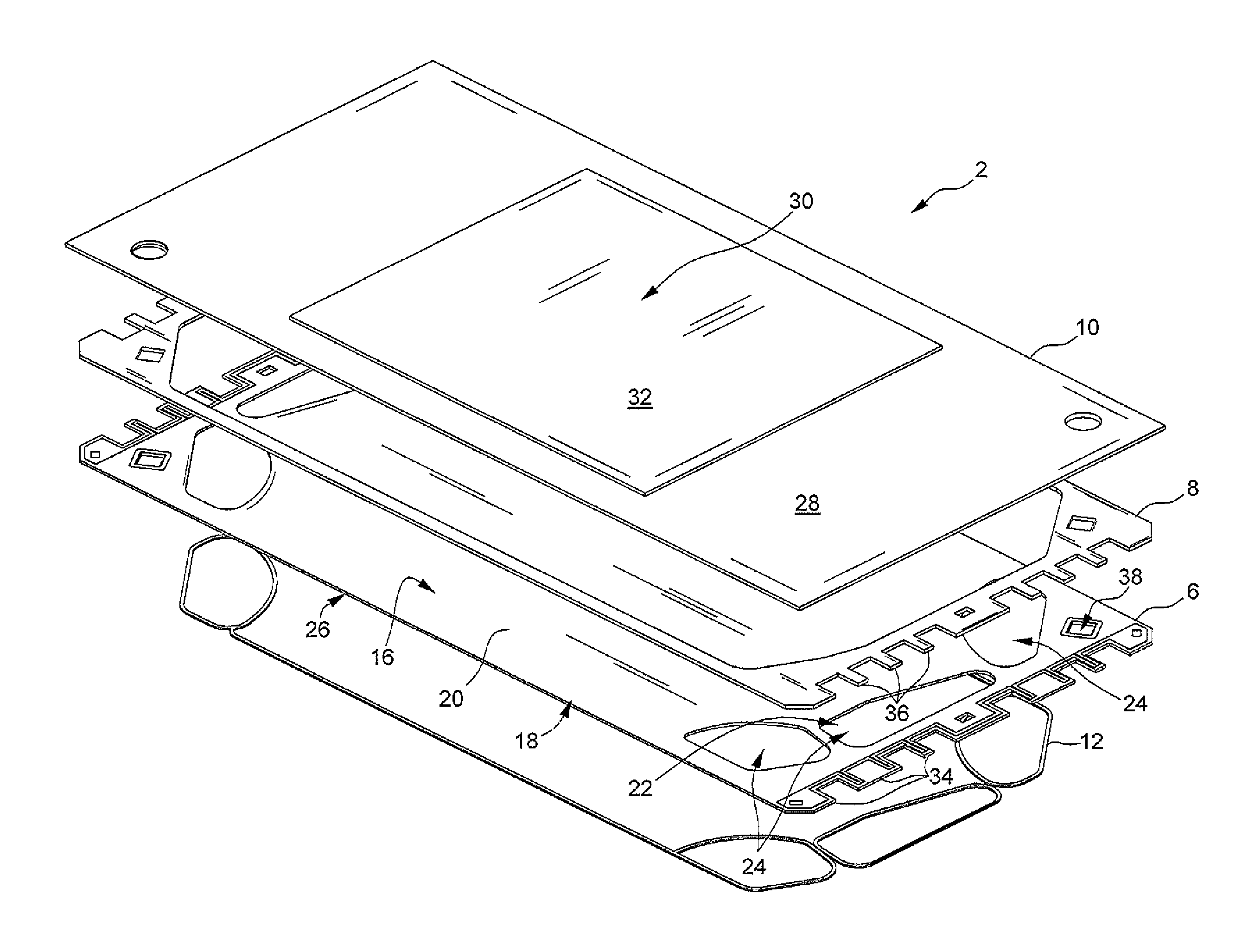
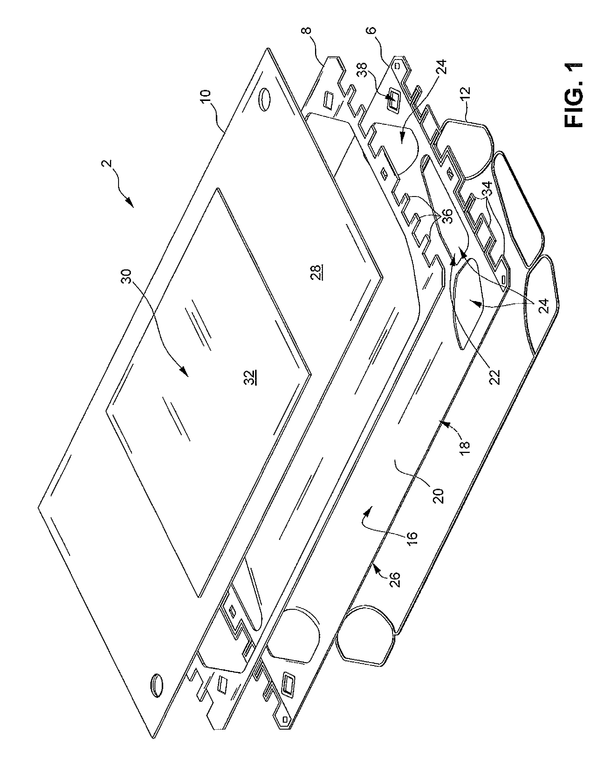
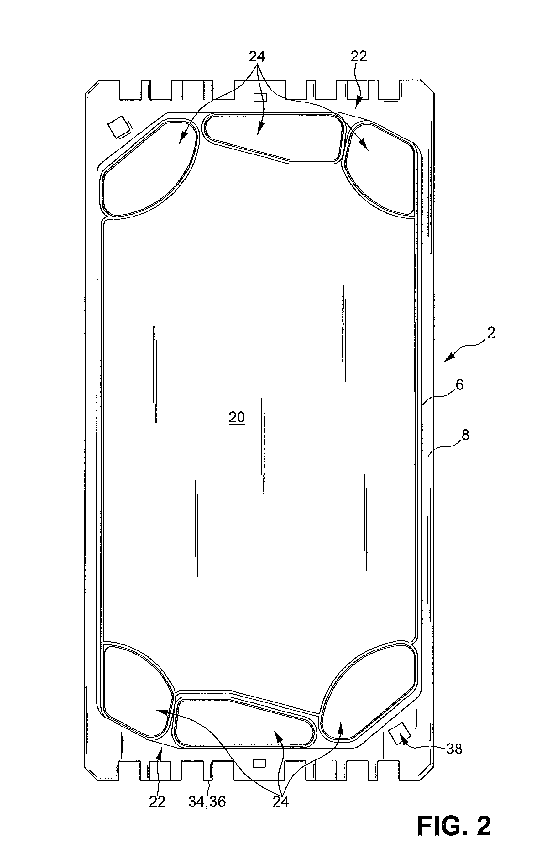
[0025]With reference to FIGS. 1-2 and 4-7, the present disclosure includes a subassembly 2 for a fuel cell 4. The subassembly 2 includes a fuel cell plate 6, an insulating spacer 8, a unitized electrode assembly 10, and an elastomeric gasket or seal 12 arranged in a stack. The subassembly 2 may be aligned in pairs to form the fuel cell 4, and a plurality of the fuel cells 4 aligned in a stack to form a fuel cell stack 14 (shown in FIG. 3).

[0026]The fuel cell plate 6 of the subassembly 2 includes a first side 16 and a second side 18. The fuel cell plate 6 may be a bipolar plate or a unipolar plate, as desired. Each of the first side 16 and the second side 18 may have a flow field 20 disposed be...


PUM


Abstract

A subassembly for a fuel cell includes a fuel cell plate having a first side and a second side. Each of the first side and the second side has a flow field disposed between a pair of headers. An insulating spacer abuts the first side of the fuel cell plate and is disposed adjacent a perimeter of the fuel cell plate. A unitized electrode assembly includes a subgasket, a membrane electrode assembly, and a pair of diffusion medium layers. The membrane electrode assembly has an electrolyte membrane sandwiched between a pair of electrodes. The membrane electrode assembly is sandwiched between the pair of diffusion medium layers. The subgasket surrounds, and is coupled to, the membrane electrode assembly. The subgasket abuts the insulating spacer. An elastomeric seal abuts the second side of the fuel cell plate.

Description

FIELD OF THE INVENTION[0001]The present disclosure relates to a fuel cell and, more particularly, to a subassembly for the fuel cell.BACKGROUND OF THE INVENTION[0002]A fuel cell has been proposed as a clean, efficient, and environmentally responsible power source for electric vehicles and various other applications. Individual fuel cells can be stacked together in series to form a fuel cell stack for various applications. The fuel cell stack is capable of supplying a quantity of electricity sufficient to power a vehicle. In particular, the fuel cell stack has been identified as a potential alternative for the traditional internal-combustion engine used in modern automobiles.[0003]One type of fuel cell is the polymer electrolyte membrane (PEM) fuel cell. The PEM fuel cell includes three basic components: an electrolyte membrane; and a pair of electrodes, including a cathode and an anode. The electrolyte membrane is sandwiched between the electrodes to form a membrane-electrode-assemb...

Claims


Application Information

Patent Timeline
IPC IPC(8): H01M8/24H01M8/10
CPCY02E60/50Y02E60/521H01M8/242H01M2008/1095H01M8/0276H01M8/028H01M8/0271H01M8/0258H01M8/0267H01M8/0273H01M8/2483
Inventor BEUTEL, MATTHEW J.JAMES, RONALD L.MILLER, DANIEL P.SPENCER, STEVEN J.
Owner GM GLOBAL TECH OPERATIONS LLC
Learn More