
Method and system of anatomy modeling for dental implant treatment planning

a dental implant and anatomy modeling technology, applied in dental surgery, instruments, analogue processes for specific applications, etc., can solve problems such as the inability to preview restorations with the actual patient anatomy, the inability to use bone and teeth combinations as aesthetic references, and the inability to use virtual teeth functionally to meet the actual needs of aesthetic evaluation

Inactive Publication Date: 2012-04-26
GUIDEMIA TECH
View PDF1 Cites 85 Cited by
  • Summary
  • Abstract
  • Description
  • Claims
  • Application Information

AI Technical Summary

Benefits of technology

[0014]The objective of this invention is to develop a methodology and the enabling algorithms to place implants, preview restorations and design surgical guides with the same reference model throughout the treatment planning workflow, regardless the underlying implant case is fully or partially edentulous, regardless whether a tissue-borne or bone-borne surgical guide is needed. This model will need to contain all oral-dental anatomy components of a patient, which are necessary for the treatment planning. The software system implementing this methodology is another part of this invention, which enables more efficient implant placements, better case assessments, and a consistent surgical guide modeling that works for all kinds of cases.
[0016]In one embodiment, the soft tissue component of a FAM is extracted from the scan of a radiographic guide (scan prosthesis, provisional denture, etc). Either a CT scan or an optical scan can be used. Alternatively, the soft tissue model is obtained by the optical scan of a plaster model or an impression. The soft tissue model and bone model are assembled into one virtual stone model. Nerve models can then further be added to this assembly. Another embodiment is to use the patient's intra-oral scan, which seems more promising in terms of accuracy and efficiency. The intra-oral scan, impression scan and plaster model scan are all referred as optical scan in the remainder of this document.

Problems solved by technology

Unfortunately, the virtual teeth are added to a model with only jaw bones and teeth, other than a model that also includes soft tissues.
This makes the virtual tooth functionality inconsistent with the actual needs of aesthetics evaluation.
Using combinations of bone and teeth as aesthetics references is not a good practice, but has been the reality in prior art since the tissue models were not available.
With the state-of-art treatment planning, the placement reference may not be the surgical guide reference, and the aesthetics reference does not actually exist in treatment planning systems, which makes it impossible to preview restorations with the actual patient anatomy.

Method used


Image

  • Method and system of anatomy modeling for dental implant treatment planning
  • Method and system of anatomy modeling for dental implant treatment planning
  • Method and system of anatomy modeling for dental implant treatment planning

Examples


Embodiment Construction

Full Anatomy Model

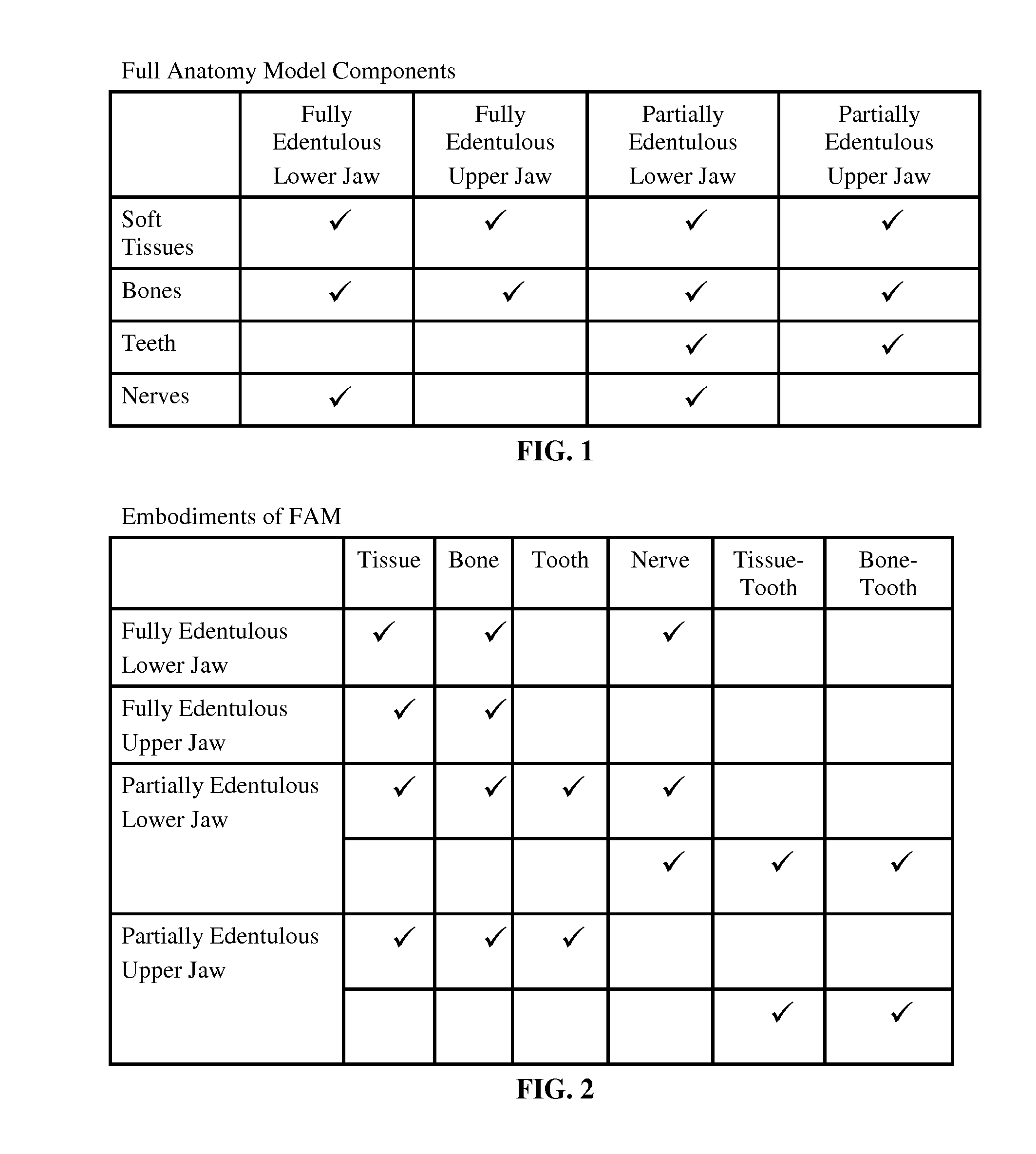
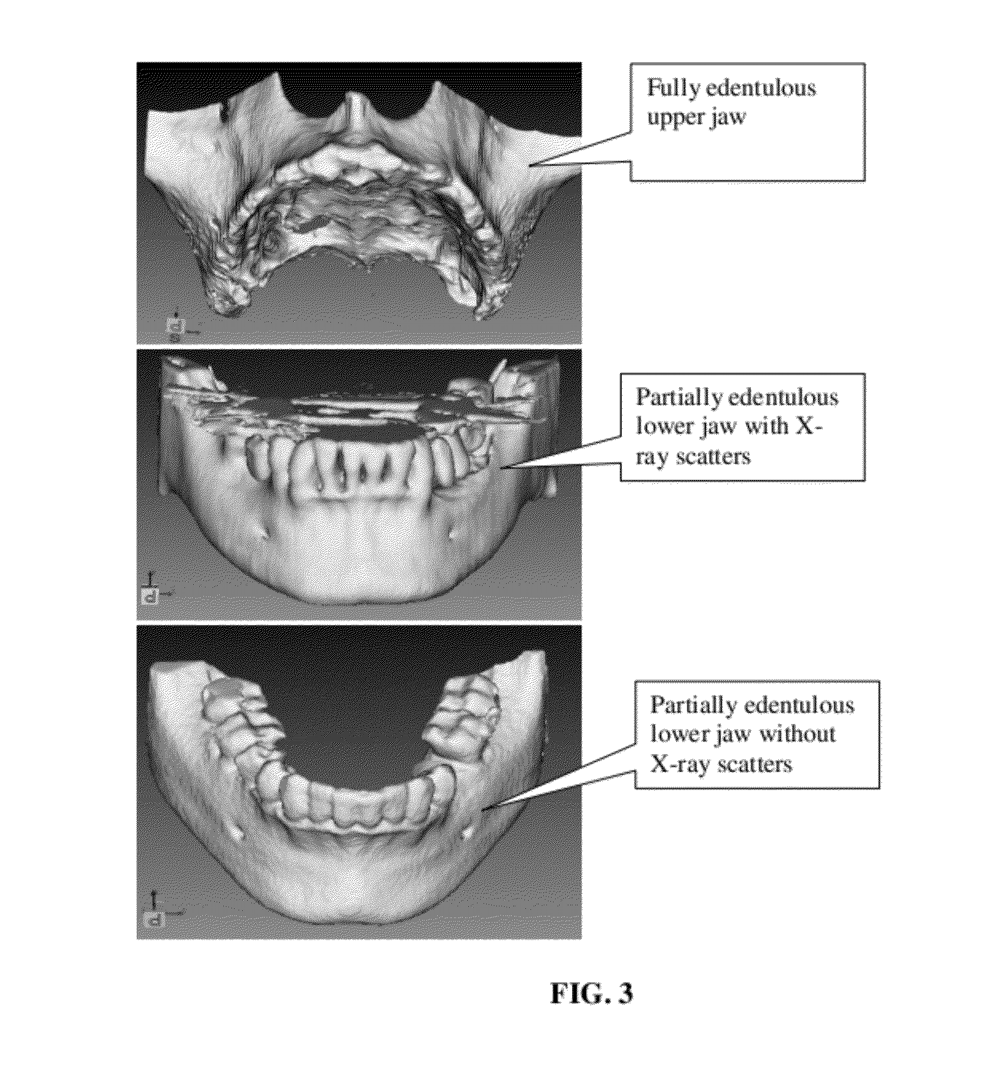
[0038]FAM is defined as a collection of geometric models representing a patient's anatomical structures including jaw bones, teeth, soft tissues and nerves. FIG. 1 shows the components of a FAM. The component for soft tissues is the main differentiator. The checkmarks indicate all the applicable components for various cases. For example, the FAM of a “Fully Edentulous Lower Jaw” case will include the soft tissues, the bones and the nerves. With a fully edentulous case, there is no remaining tooth, so the components will be simply for the bones, soft tissues and nerves. For an upper jaw, there is no nerve model.

[0039]The components of a FAM are not necessarily separated geometric models. The actual embodiments can combine anatomical structures in one model or more. Specifically, it is very common that the soft tissues and teeth are combined into one model, namely, “tissue-tooth” model; the bone and teeth are combined as “bone-tooth” model. In FIG. 2, the basic embod...


PUM


Abstract

This invention introduces an oral-dental anatomy modeling method and an implant treatment planning system based on a full anatomy model (FAM). Dental Implant Treatment Planning systems place implants on 2D slices of DICOM files, and sometimes on 3D models of bones and remaining teeth. Because the final look and feel of implants and restorations depend on how well they go along with the remaining teeth and soft tissues, treatment planning without tissue model presents safety and aesthetics risks. A FAM consists of models for bones, teeth, soft tissues and nerves. They are created from CT and optical scans, and assembled together with model registration techniques. The tissue model is the real differentiator. A treatment planning system uses FAM as a unique reference throughout the workflow. Its implant placement, restoration preview and surgical guide design are all based on FAM.

Description

CROSS-REFERENCE TO RELATED APPLICATIONS[0001]U.S. patent application 12,860,019Aug. 20, 2010GaoU.S. patent application 12,795,045Jun. 7, 2010GaoU.S. patent application 12,776,544May 10, 2010GaoREFERENCE CITEDUS Patent Documents[0002]US 2007 / 0059665 A1Mar. 15, 2007Orentlicher et al.US 2008 / 0193896 A1Aug. 14, 2008Yang et al.U.S. Pat. No. 7,758,345B1Jul. 20, 2010ChristensenOTHER PUBLICATIONS[0003]Materialise, Dual scan protocol—Cone Beam CT, 2010[0004]Philippe B. Tardieu, DDS, Alan L. Rosenfeld, DDS, The Art of Computer-guided implantology. Quintessence Publishing Co, Inc, 2009[0005]Zhengyou Zhang, Iterative point matching for registration of free-form curves and surfaces Source. International Journal of Computer Vision, Volume 13, Issue 2 (October 1994)[0006]Luis Ibanez, Will Schroeder, et al. ITK software guide, Second Edition, the Insight Software Consortium, 2005FIELD OF THE INVENTION[0007]This invention concerns the methodology of computerized image-guided dental implant treatment...

Claims


Application Information

Patent Timeline
IPC IPC(8): A61C13/36G06G7/60
CPCA61C1/084A61C13/01A61C13/0004B33Y50/00B33Y80/00
Inventor GAO, FEI
Owner GUIDEMIA TECH
Learn More