Drill-Bit Seismic With Downhole Sensors

a technology of seismic and sensors, applied in the field of drill-bit seismic with downhole sensors, can solve the problems of poor subsurface image quality, low accuracy of source signal estimation, and low spatial accuracy of obtained images

Active Publication Date: 2012-05-03
BAKER HUGHES INC
View PDF48 Cites 22 Cited by
  • Summary
  • Abstract
  • Description
  • Claims
  • Application Information

AI Technical Summary

Problems solved by technology

The obtained image often suffers in spatial accuracy, resolution and coherence due to the long travel paths between source, reflector, and receiver.
In particular, due to the two-way passage of seismic signals through a highly absorptive near surface weathered layer with a low, laterally varying velocity, subsurface images are poor quality.
The source signal travels a long way through the drillstring enhanced estimation off the source signal may not be accurate.

Method used


Image

  • Drill-Bit Seismic With Downhole Sensors
  • Drill-Bit Seismic With Downhole Sensors
  • Drill-Bit Seismic With Downhole Sensors

Examples


Embodiment Construction

[0021]The present disclosure is described with reference to acoustic sensors used in seismic while drilling methodology. However, this is not intended to be a limitation, and the method generally described herein can also be used with other types of sensor measurements.

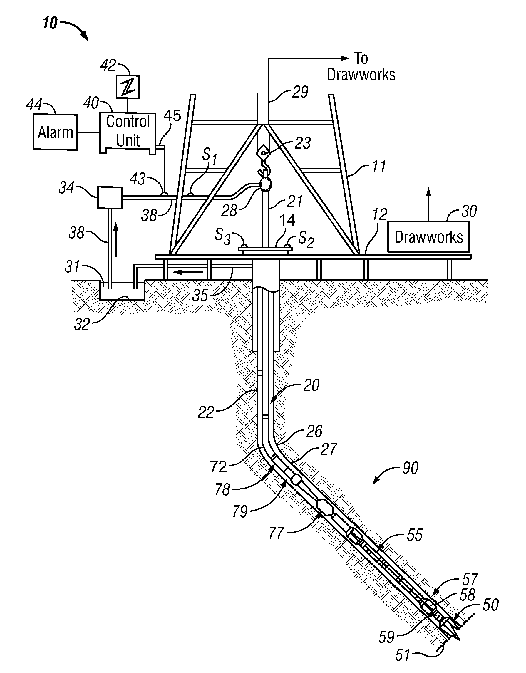
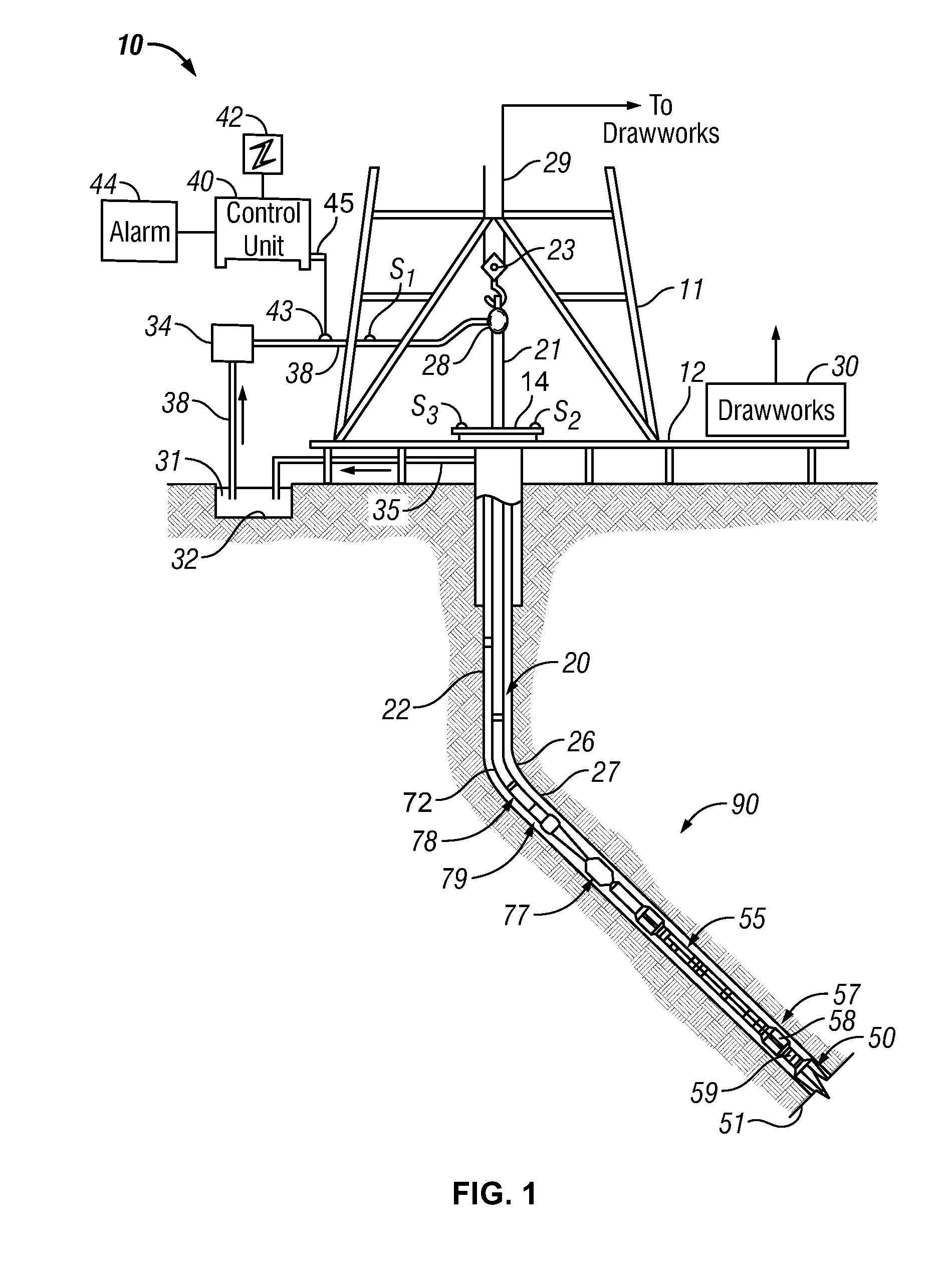
[0022]FIG. 1 shows a schematic diagram of a drilling system 10 with a drillstring 20 carrying a drilling assembly 90 (also referred to as the bottom hole assembly, or “BHA”) conveyed in a “wellbore” or “borehole”26 for drilling the borehole. The drilling system 10 includes a conventional derrick 11 erected on a floor 12 which supports a rotary table 14 that is rotated by a prime mover such as an electric motor (not shown) at a desired rotational speed. The drillstring 20 includes a tubing such as a drill pipe 22 or a coiled-tubing extending downward from the surface into the borehole 26. The drillstring 20 is pushed into the borehole 26 when a drill pipe 22 is used as the tubing. For coiled-tubing applications, a tubi...


PUM


Abstract

A drill-bit seismic method where the seismic receivers are located in the BHA. The data detected by these receivers is processed by a downhole processing unit in order to estimate the interval velocity of the seismic wave between the sensors and between the bit and a sensor. Additionally, the processed data might provide the distance to a seismic reflector close to the borehole and the average seismic velocity between the well and this reflector. The processed data can be transmitted to surface location by mud-pulse telemetry. The pilot signal can be also used to process seismic data recorded by receivers located at the earth surface (or close to it).

Description

CROSS-REFERENCE TO RELATED APPLICATIONS[0001]This application is a continuation in part of U.S. patent application Ser. Nos. 13 / 093,326 and 13 / 093,289 filed on Apr. 25, 2011, with priority claims to U.S. provisional patent application Ser. No. 61 / 408,106 filed on Oct. 29, 2010; a priority claim to U.S. provisional patent application Ser. No. 61 / 408,144 on Oct. 29, 2010; and a priority claim to U.S. provisional patent application 61 / 408,119 filed on Oct. 29, 2010.BACKGROUND OF THE DISCLOSURE[0002]1. Field of the Disclosure[0003]The present disclosure relates to an improved method of determining, while drilling in the earth with a drill bit, the velocity of seismic signals and the positions of geologic formations in the earth. More particularly, it relates to a method for improving the quality of the acquired data.[0004]2. Description of the Related Art[0005]Conventional reflection seismology utilizes surface sources and receivers to detect reflections from subsurface impedance contra...

Claims


Application Information

Patent Timeline
Patent Type & Authority Applications(United States)
IPC IPC(8): E21B47/00
CPCE21B47/01G01V1/42G01V1/303E21B49/003E21B47/013
Inventor COMAN, RADUKUMAR, SUNIL
Owner BAKER HUGHES INC
Why Eureka
Try Eureka