Tube target

a technology of target and tube, applied in the field of target, can solve the problems of destroying the target, affecting the production of target materials, and affecting the effect of sputtering of 30% to 40% of the material of which it is composed, and achieve the effect of relieving stress

Active Publication Date: 2012-05-03
PROTECH MATERIALS INC
View PDF4 Cites 3 Cited by
  • Summary
  • Abstract
  • Description
  • Claims
  • Application Information

AI Technical Summary

Benefits of technology

[0011]The invention therefore addresses the problem of relieving the stresses between the inside and the outside of the target.

Problems solved by technology

These planar targets, however, have the disadvantage that only approximately 30% to 40% of the material of which it is comprised are effectively sputtered.
Their production, however, is more difficult than the production of planar targets.
Since, however, the target also expands due to the high temperatures of the plasma, radial tear-off forces occur, which lead to damage or even destruction of the target making uniform coating no longer possible.

Method used


Image

  • Tube target
  • Tube target
  • Tube target

Examples


Embodiment Construction

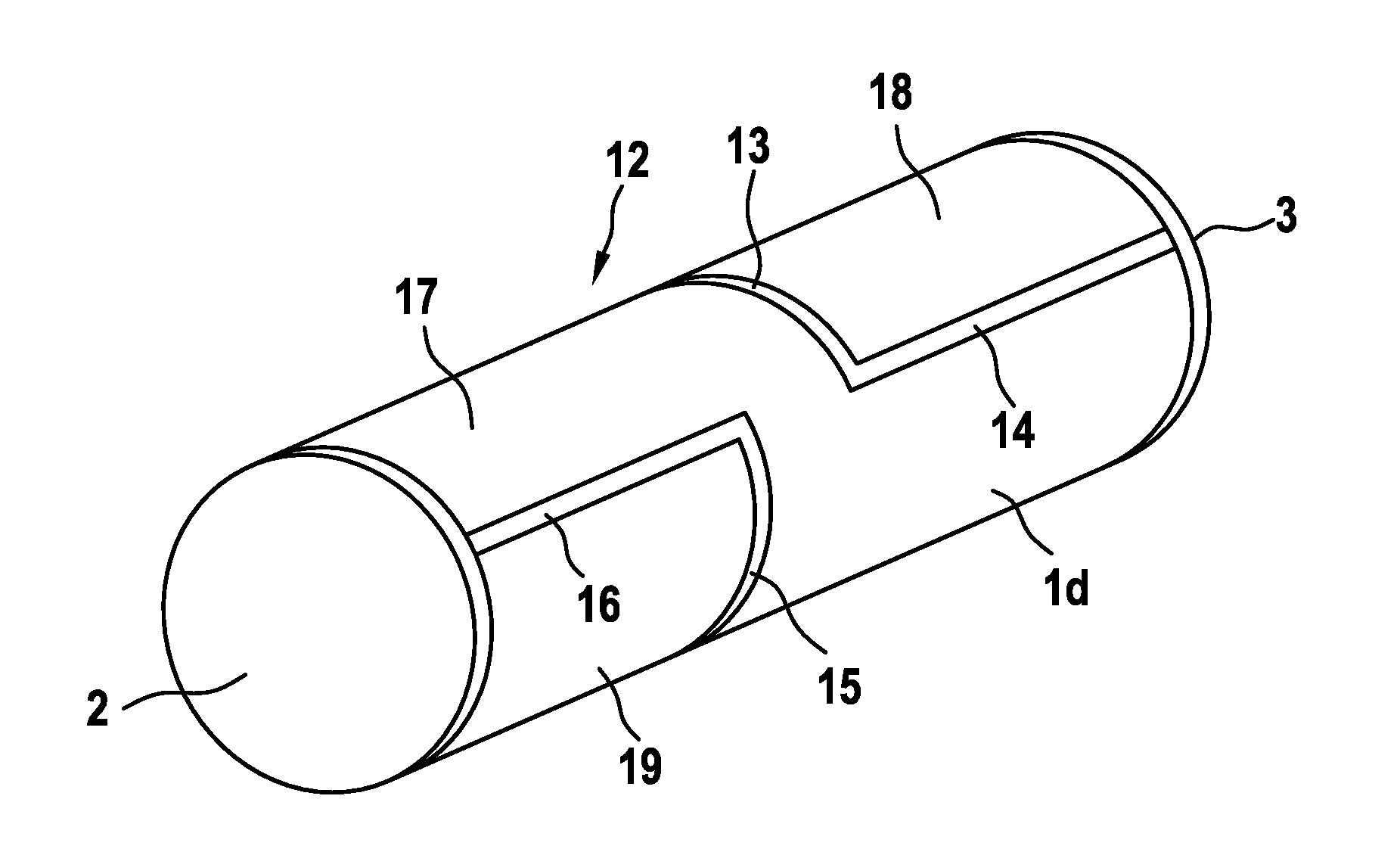
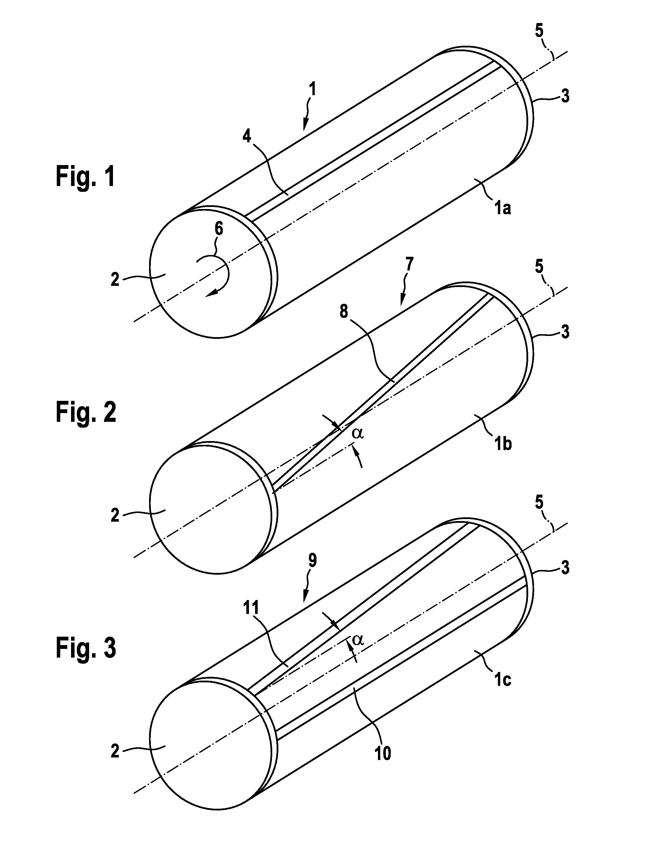
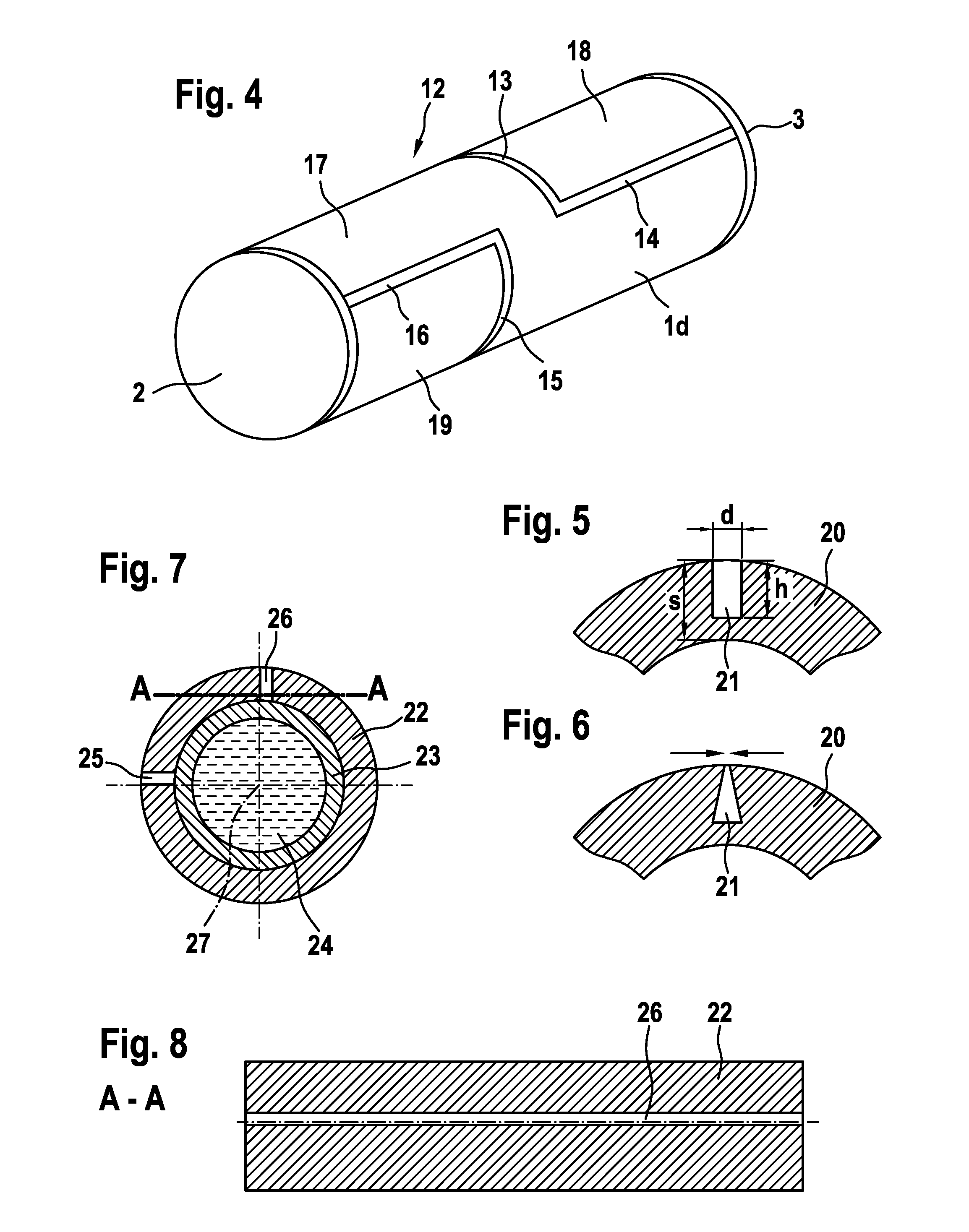
[0028]FIG. 1 depicts in perspective view and schematically a tube target 1. For the sake of clarity, it is here closed off with caps 2, 3. This tube target 1 comprises a carrier tube, not evident in FIG. 1, which is encompassed by a target 1a. This target 1a is provided with a groove 4 extending parallel to a rotational axis 5 of the tube target 1. An arrow 6 indicates the rotational direction. The depth of the groove 4 is not specified.

[0029]During the sputter process a plasma is located above or beneath a portion of the tube target 1. This plasma is substantially as long as the tube target 1, however has a diameter less than the diameter of the tube target 1. When the tube target 1 rotates, the groove 4 is located with its entire length above or beneath the plasma when [the groove] travels below or above the plasma. The immersion, dwelling and exiting of the groove 4 into, in or from the plasma changes the surface of target 1a facing the plasma and therewith the plasma impedance. ...


PUM

PropertyMeasurementUnit
lengthaaaaaaaaaa
lengthaaaaaaaaaa
thicknessaaaaaaaaaa

Abstract

The invention relates to a tube target (50) for sputtering, with a target (46) disposed on a cylindrical carrier tube. This target (46) is divided into several segments. The target (46) includes at least one groove (51-54) extending obliquely with respect to its rotational axis.

Description

FIELD OF THE INVENTION[0001]This invention relates to a tube target according to the preamble of claim 1.BACKGROUND OF THE INVENTION[0002]Most sputter targets used in the past are so-called planar targets which are formed circularly or rectangularly. These planar targets, however, have the disadvantage that only approximately 30% to 40% of the material of which it is comprised are effectively sputtered.[0003]To increase the effectiveness of sputtering, tubular targets are increasingly employed. Their production, however, is more difficult than the production of planar targets.[0004]A method for the production of a sputtering target is already known, in which, first, a cylindrical carrier element is introduced into a casting mold such that an empty volume is formed between the carrier element and the casting mold (EP 0 500 031 B1).[0005]A target material is hereupon filled into this empty volume between the carrier element and the casting mold and the casting mold is closed. An isost...

Claims


Application Information

Patent Timeline
Patent Type & Authority Applications(United States)
IPC IPC(8): C23C14/34
CPCC23C14/3407H01J37/3491H01J37/3423H01J37/342C23C14/34
Inventor WURCZINGER, DIETER
Owner PROTECH MATERIALS INC
Why Eureka
Try Eureka