Device and Method for Pressure Control of Electric Injection Molding Machine

Inactive Publication Date: 2012-05-03
AKASAKA NORIYUKI
View PDF3 Cites 14 Cited by
  • Summary
  • Abstract
  • Description
  • Claims
  • Application Information

AI Technical Summary

Benefits of technology

[0103]By applying a high-gain observer for a model of electric-motor driven injection molding machines which has injection pressure as a state variable, a high-precision pressure detection with small time-lag becomes possible without using a pressure detector. By using the high-gain observer the two requirements (1) and (2) described in paragraph {0008} for controlling pressure of electric-motor driven injection molding machines can be satisfied and also the four disadvantages described in Background Art (paragraph{0051}) can be avoided.

Problems solved by technology

However, as excessive injection velocity brings about excessive polymer pressure and mold defects, polymer pressure in the injection process is constrained under a given pressure limit pattern.
In FIG. 3, transfer time t1 from injection to pressure application is specified by an operator, so the time t1 should coincide with the time at which the cavity is filled up with polymer melt, but it is difficult for an operator to set the time t1 at the exact time.
In the estimation method of polymer pressure by equation (6), an error of angular acceleration of motor a due to the numerical differential operation and errors of FLOSS and TU bring about the error of the estimated polymer pressure.

Method used


Image

  • Device and Method for Pressure Control of Electric Injection Molding Machine
  • Device and Method for Pressure Control of Electric Injection Molding Machine
  • Device and Method for Pressure Control of Electric Injection Molding Machine

Examples


example

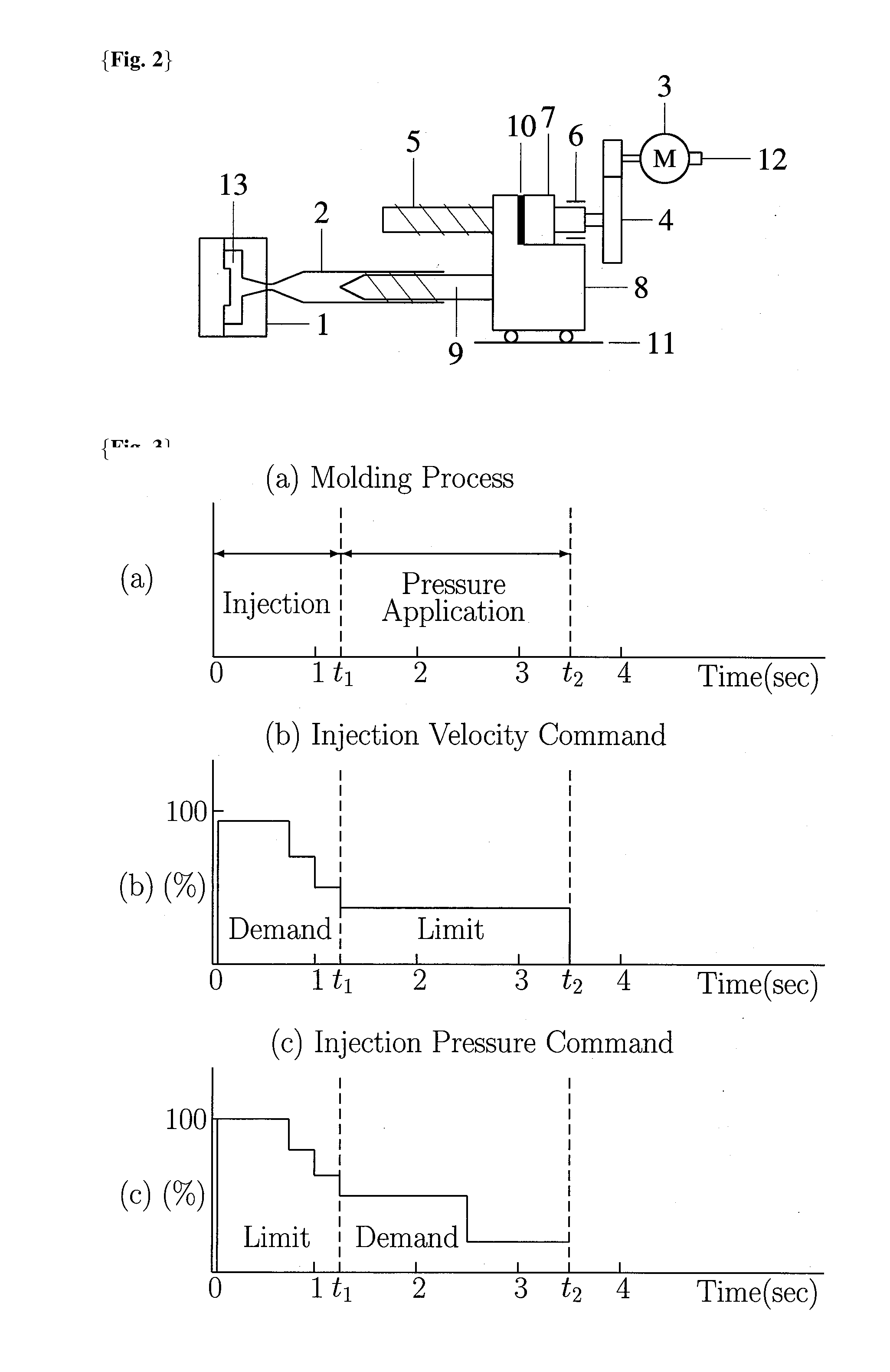
[0111]FIG. 5 is a view which shows an injection and pressure application mechanism without using a pressure detector. As the mechanism in FIG. 5 consists of the parts with the same reference signs as in FIG. 2 except a pressure detector 10, explanations of FIG. 5 are replaced by those of FIG. 2 described in Background Art (paragraph{0004}˜{0006}).

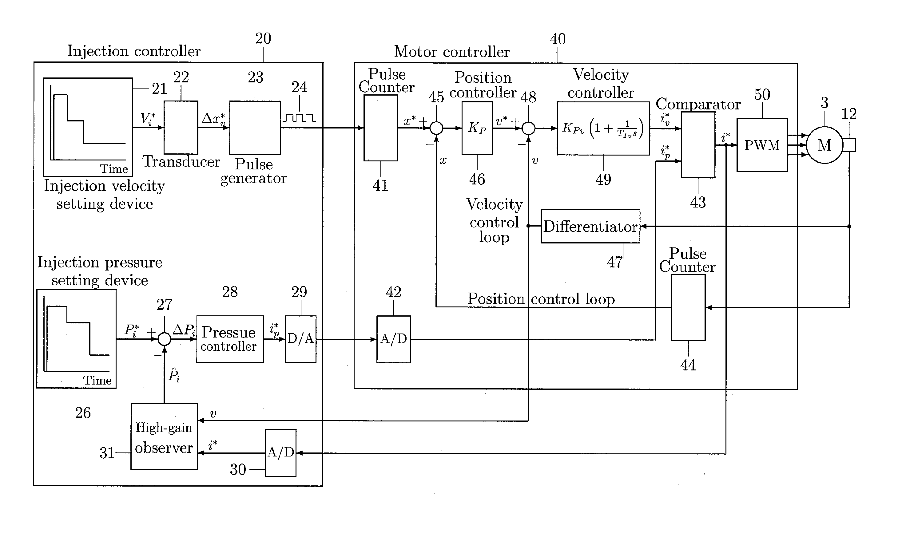
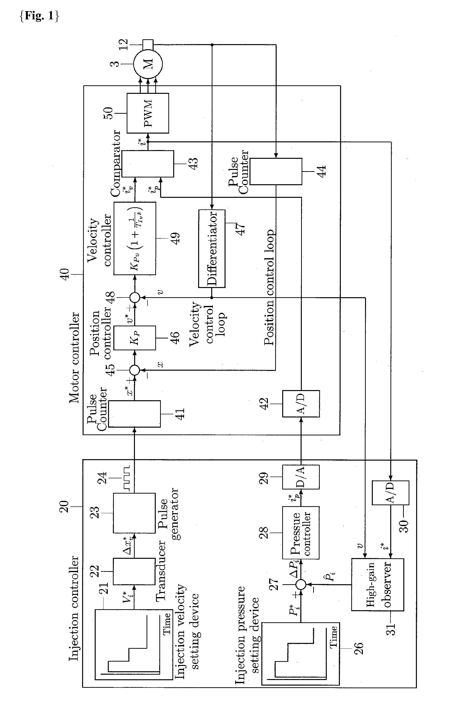
[0112]FIG. 2 is an example of a controller of an electric-motor driven injection molding machine using a high-gain observer as an injection pressure detecting means according to an embodiment of the present invention and shows a block diagram of a system configuration for the controller. The controller consists of an injection controller 20 which contains a high-gain observer 31 and a motor controller (servoamplifier) 40.

[0113]The injection controller 20 is explained as follows. The injection controller 20 executes a control algorithm at a constant time interval Δt and feeds a discrete-time control demand to the motor controller 40. The inj...


PUM

PropertyMeasurementUnit
Pressureaaaaaaaaaa

Abstract

{Problem}The exact method with small time-lag of detecting injection pressure for controlling pressure in an electric-motor driven injection molding machine without using a pressure detector has been asked for because the pressure detector is very expensive, necessitates troublesome works for mounting, an electric protection against noise and the works for zero-point and span adjustings and causes a complicate mechanical structure.{Solution}The present invention uses a high-gain observer which contains the discrete-time arithmetic expressions derived from a mathematical model of an injection and pressure application mechanism in an electric-motor driven injection molding machine consisting of a state equation and an output equation and outputs an estimate of injection pressure, which is one of the state variables of the above state equation, by using an injection velocity signal and a servomotor current demand signal or actual motor current signal as inputs. The high-gain observer obtains the exact injection pressure estimate with very small time-lag without using a pressure detector. Thus the estimate of injection pressure fed by the high-gain observer can be adopted as a feedback signal of actual injection pressure for controlling injection pressure.

Description

TECHNICAL FIELD[0001]This invention is concerning an apparatus and a method for controlling pressure in an electric-motor driven injection molding machine.BACKGROUND[0002]AC servomotors are becoming used for middle-sized injection molding machines heretofore driven by hydraulic actuators (clamping force>3.5 MN) that have high precision, quick response and higher power which are obtained by performance improvements of permanent magnets and cost reductions.[0003]An injection molding machine consists of a plasticizier in which resin pellets are melted by friction heat generated by plasticizing screw revolution and stored at the end of a barrel, an injector in which an amount of melted polymer is injected into a metal mold at a given velocity and a given dwell pressure is applied, and a clamper in which the metal mold is clamped and opened, all using AC servomotors drive system. FIG. 2 shows a view of an injection molding mechanism using an AC servomotor.[0004]On an injection machine...

Claims


Application Information

Patent Timeline
IPC IPC(8): B29C45/77
CPCB29C45/77B29C2045/1792B29C2945/76187B29C2945/76214B29C2945/7611B29C2945/76033
Inventor AKASAKA, NORIYUKI
Owner AKASAKA NORIYUKI
Why Eureka
Try Eureka