Energy efficient cascade of sensors for automatic presence detection

a cascade of sensors and automatic detection technology, applied in the field of cascade connected sensors, can solve the problems of people being terrified, future true readings being ignored, damage to your car, etc., and achieve the effect of low overall power consumption, accurate and more power consumption, and high accuracy

Inactive Publication Date: 2012-05-03
SIGNIFY HLDG BV +1
View PDF4 Cites 28 Cited by
  • Summary
  • Abstract
  • Description
  • Claims
  • Application Information

AI Technical Summary

Benefits of technology

[0016]A problem to be solved with the present invention is to create a method and a system that maintains a low overall power consumption while obtaining high accuracy through reducing both the number of false negative and false positive readings.
[0017]According to one aspect of the invention the problem is solved by connecting in cascade different kinds of sensors, and then only gradually activating a more accurate and more power consuming sensor, when simpler sensors have indicated presence, exploiting the information obtained by these sensors to decide whether further, even more power consuming analysis is requested, thereby keeping the overall power consumption of the presence detection system at a low level.
[0018]Another aspect of the invention is to further reduce the overall power consumption by deactivating each intermediate sensor as a more accurate sensor is activated.
[0019]Another aspect of the invention is to further reduce the number of false negative readings by activating the ultimate sensor in the cascade randomly or periodically, even if the preceding sensor has not detected presence.

Problems solved by technology

For a car parking aid, a false negative reading may lead to damage to your car, while a false positive reading is probably only a minor nuisance.
A false positive reading in a personal safety system on the contrary, may lead to people being terrified.
Repeated false positive readings in a surveillance system might have a “cry wolf” effect on a security officer assigned to investigate the surveyed area, leading to future true readings being ignored.
False positive readings triggering heating or lighting systems will increase power consumption significantly.
Most of the time these false readings have natural causes, but sometimes the functioning of the sensor is deliberately tampered with.
Some applications are especially prone to tampering, e.g. surveillance or burglary alarms, and therefore it is desirable that sensors used in such applications be difficult to manipulate.
Therefore presence detectors based on this technology are difficult to implement, unpractical, and power consuming, because of the power demands of the multitude of emitted IR light beams.
In addition the system will register any object breaking a beam, and cannot distinguish a dead object from a human being.
Used as a human presence detector, the IR beam detector will cause a high rate of false positive readings.
However, a PID based system will potentially give an indication based on anything moving within its field of view, i.e. a high rate of false positive readings.
Usually, a PID cannot distinguish between a human and other moving objects with any accuracy; if a moving object stops, and becomes immobile, the PID may lose track of it.
Lastly, continuous bright light can saturate a PID sensor and render it unable to register further information.
This feature makes it less reliable as a presence detector outdoors, and makes it relatively easy to manipulate.
The ultrasonic sensor is less good at detecting immobile objects.
Further, an ultrasonic sensor based system may be prone to manipulation, because of the fact that surface shape, density or consistency of material covering an object can muffle the echo sufficiently to render the object invisible to the ultrasonic sensor.
Audio / video scene analysis is a very complex process.
In order to achieve robustness, algorithms have to be computationally demanding.
The average power consumption needed to run such algorithms on a chip continuously is substantial.
As can be seen in the above examples, high accuracy typically comes with high power consumption.

Method used


Image

  • Energy efficient cascade of sensors for automatic presence detection
  • Energy efficient cascade of sensors for automatic presence detection
  • Energy efficient cascade of sensors for automatic presence detection

Examples


first embodiment

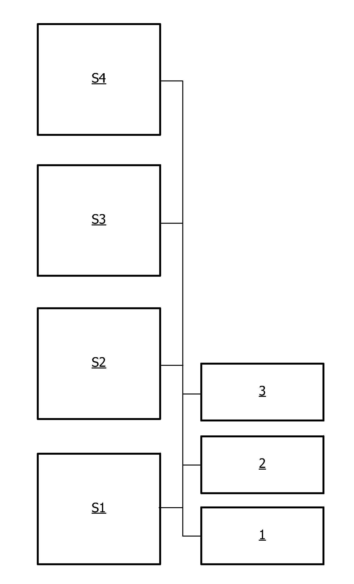
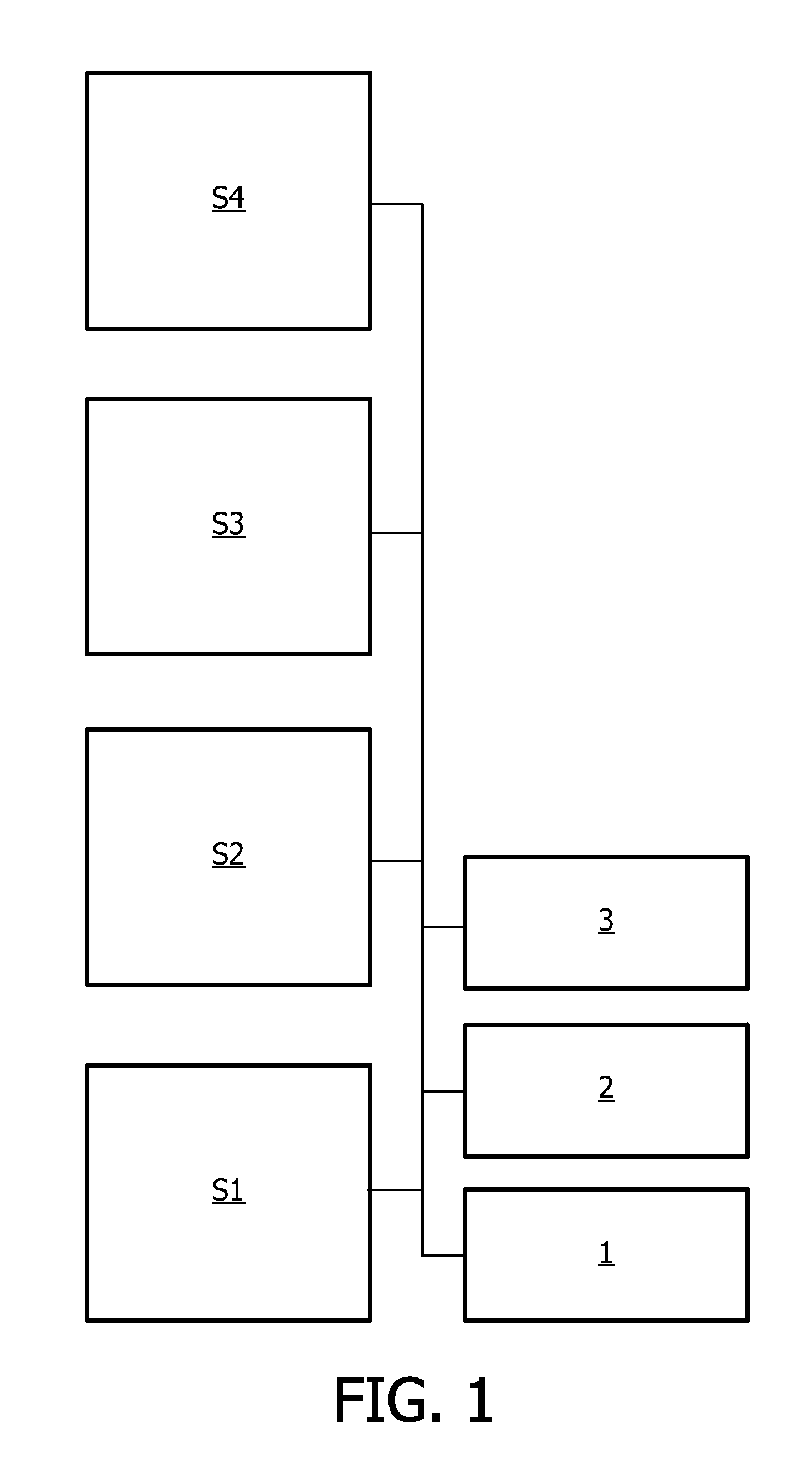
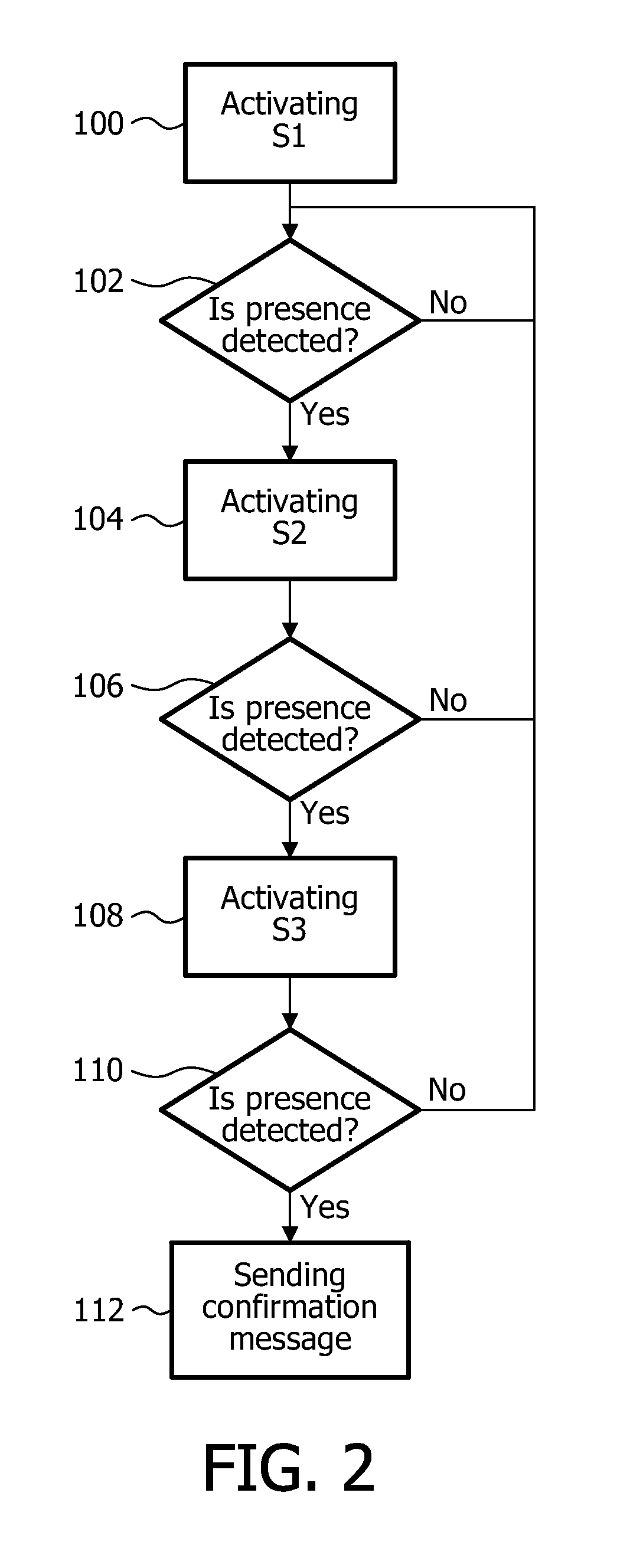
[0039]FIG. 2 is a flow chart illustrating the method according to the present invention. In a first step 100 the control unit 2 depicted in FIG. 1 activates the first sensor s1. Thereafter, the control unit 2, in step 102, waits for the first sensor s1 to detect presence. If presence is detected, the control unit 2 activates the second sensor s2 in step 104. If the first sensor s1 does not detect presence it will keep waiting until it does. Thereafter, in step 106, the control unit 2 waits a predetermined time for the second sensor s2 to detect presence. The predetermined time is set such that it is sufficiently long for the second sensor s2 to make a proper scanning. If no detection is made by the second sensor s2 within that predetermined time, the control unit 2 returns to step 102.

[0040]However, if the second sensor s2 confirms the first sensor's s1 detection, the control unit 2 will activate the third sensor s3 in step 108. In step 110, the control unit 2 waits a predetermined ...

second embodiment

[0041]FIG. 3 is a flow chart illustrating the method according to the present invention. The second embodiment corresponds substantially to the one described in conjunction with FIG. 2. Thus, steps 120-132 are identical with steps 100-112 in FIG. 2 and are therefore not described again. However, the second embodiment also includes a step 134, which runs in parallel with the method depicted in FIG. 2. In the first embodiment a subsequent sensor is only activated if a previous sensor has detected presence. As an alternative, a sensor may also be intermittently or randomly activated in step 134. This will be beneficial if the first or second sensor is malfunctioning, giving a false reading or is being tampered with, since the third sensor s3 will be activated with some predetermined frequency, or randomly, even if the previous sensors have not detected presence.

[0042]Also FIG. 4 shows an embodiment of the method that substantially corresponds to the embodiment shown in FIG. 2 together ...


PUM


Abstract

The present invention relates to a method and a system for detecting presence in a predefined space. The system comprises cascade connected sensors (s1, s2, . . . , sn), an output device (1), a control unit (2) and a processing unit (3). The method comprises the steps of activating a first sensor (s1) in the cascade and waiting until the first sensor detects presence. When presence is detected, a successive sensor (s2, . . . , sn) in the cascade is activated, and when the successive sensor (s2, . . . , sn) also detects presence the step of activating the successive sensor is repeated until all sensors in the cascade have been activated. If the successive sensor (s2, . . . , sn) does not detect presence the method returns to the waiting step of the first sensor. When the ultimate sensor in the cascade (sn) detects presence, a confirmation message is sent to the output device (1).

Description

TECHNICAL FIELD[0001]The present invention relates generally to a method and a system for detecting presence, and more specifically to a system of cascade connected sensors, that minimize the energy consumption while maintaining high detection accuracy.BACKGROUND OF THE INVENTION[0002]Automatic presence detection is available for different purposes, such as building control, lighting adjustment or heating control, surveillance systems, burglar alarms, personal safety systems or car parking aids.[0003]Even though accuracy is important for all these applications, different aspects of accuracy are important, and for different reasons. For a car parking aid, a false negative reading may lead to damage to your car, while a false positive reading is probably only a minor nuisance. A false positive reading in a personal safety system on the contrary, may lead to people being terrified. Repeated false positive readings in a surveillance system might have a “cry wolf” effect on a security of...

Claims


Application Information

Patent Timeline
Patent Type & Authority Applications(United States)
IPC IPC(8): G05B23/02
CPCG08B13/00G08B13/19695G08B29/188H05B37/0227Y02B20/44H05B47/115H05B47/13Y02B20/40
Inventor GRITTI, TOMMASO
Owner SIGNIFY HLDG BV
Why Eureka
Try Eureka