Eureka AIR delivers breakthrough ideas for toughest innovation challenges, trusted by R&D personnel around the world.

Method and system for compact efficient laser architecture

Active Publication Date: 2012-05-03
LAWRENCE LIVERMORE NAT SECURITY LLC
View PDF7 Cites 9 Cited by
  • Summary
  • Abstract
  • Description
  • Claims
  • Application Information

AI Technical Summary

Benefits of technology

[0012]Embodiments of the present invention provide an amplifier module in which the number of optics is reduced in comparison with conventional designs while increasing the efficiency with which pump light is delivered to the amplifier slabs, which can be suitable for high peak power and high average power applications (e.g., 23.3 cm×23.3 cm in the transverse dimensions). Additionally, embodiments of the present invention increase the depth of field in comparison with conventional designs, enabling the use of a number of amplifier slabs, for example, ten amplifier slabs per amplifier head. Embodiments of the present invention are not limited to ten amplifier slabs and fewer or greater numbers can be utilized as appropriate to the particular implementation. Some embodiments reduce beam distortion to provide a generally “square” beam, which is pumped using diode arrays that are imaged to the center of the amplifier head.

Problems solved by technology

Several factors, however, make its long-term sustainability difficult.
Thus, significant technical challenges remain to achieve an economy powered by pure ICF energy.

Method used


Image

  • Method and system for compact efficient laser architecture
  • Method and system for compact efficient laser architecture
  • Method and system for compact efficient laser architecture

Examples


Embodiment Construction

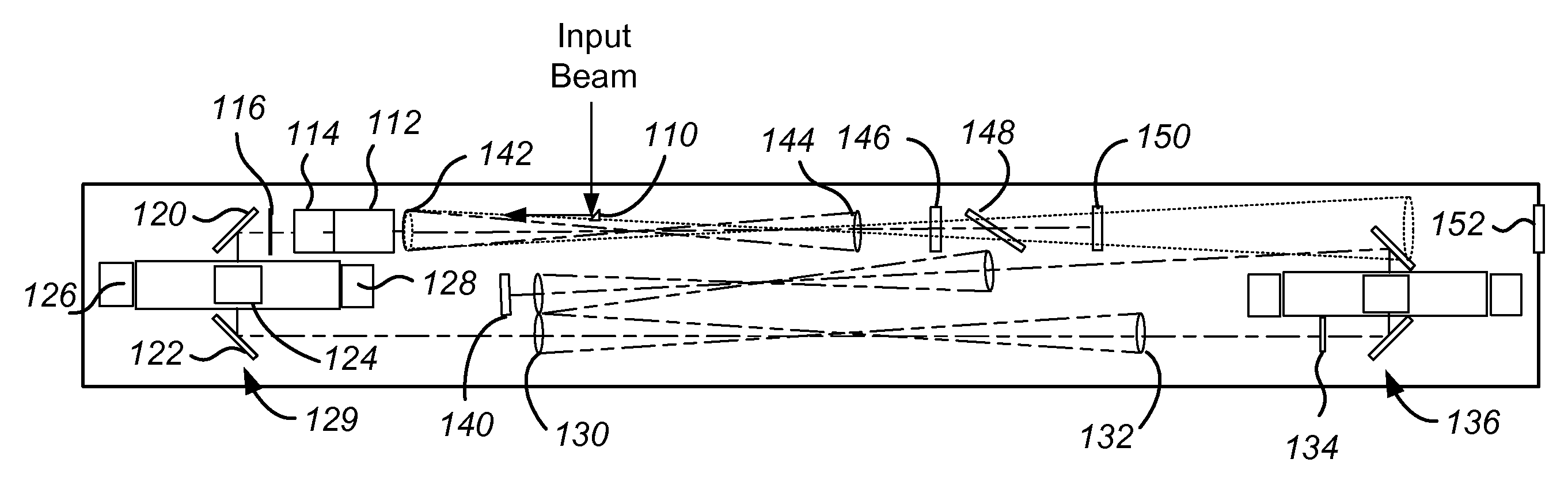
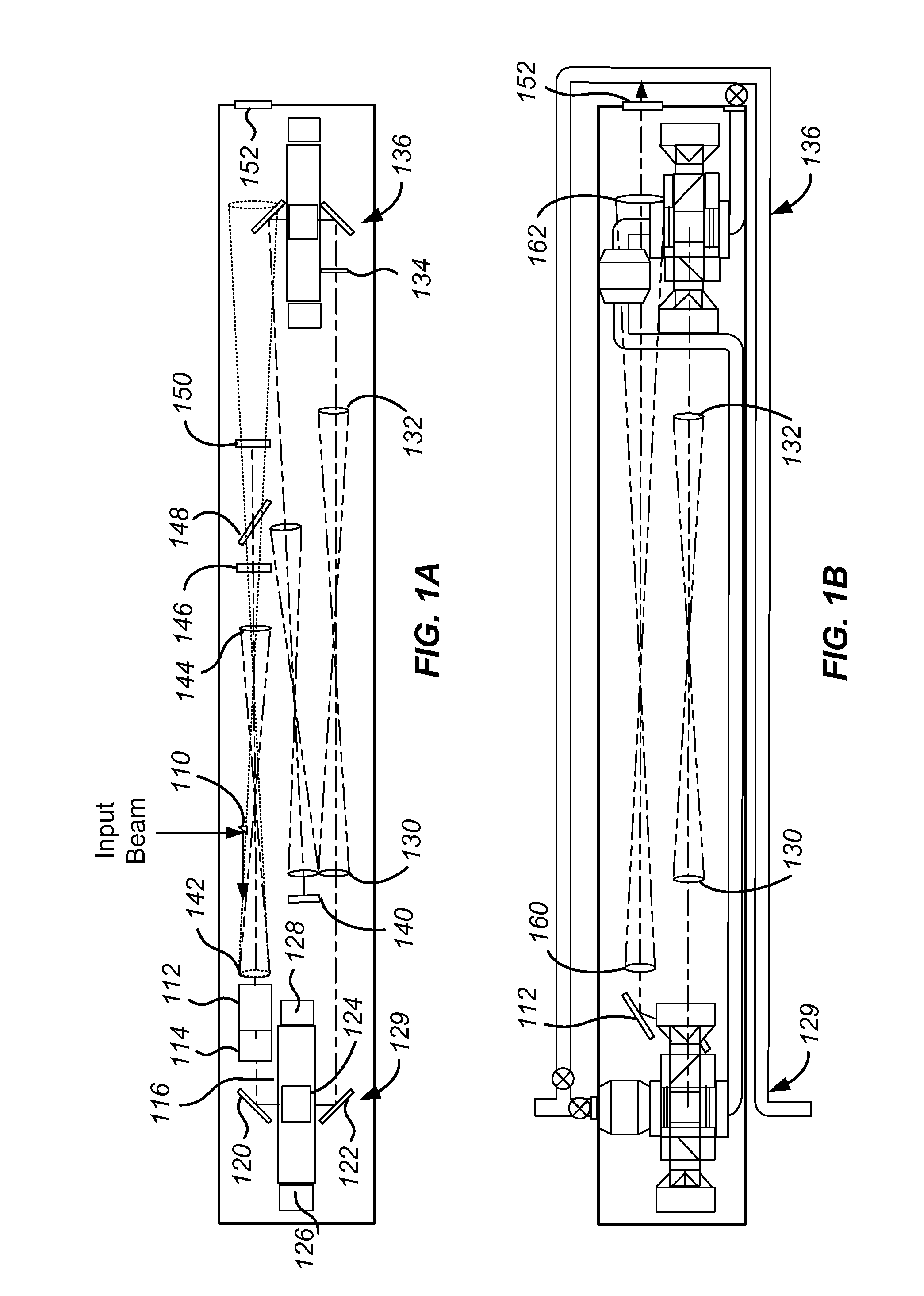
[0027]Embodiments of the present invention relate to laser systems. More specifically, the present invention relates to methods and systems for generating high power laser beams using a four-pass amplifier architecture. Merely by way of example, the invention has been applied to an amplifier assembly utilizing either transverse pumping or end pumping of amplifiers in a compact architecture. The methods and systems can be applied to a variety of other laser amplifier architectures and laser systems.

[0028]As described more fully below, embodiments of the present invention provide an amplifier module operable to amplify one, two, four, or more beams in a close coupling arrangement to form, in a four-beam arrangement, a “quad” amplifier utilizing either end or transverse pumping of the amplifier slabs. Accordingly, as shown in Table 1 below, embodiments of the present invention provide a single or quad amplifier module with reduced volume per beam aperture in comparison with conventiona...


PUM


Abstract

A laser amplifier module having an enclosure includes an input window, a mirror optically coupled to the input window and disposed in a first plane, and a first amplifier head disposed along an optical amplification path adjacent a first end of the enclosure. The laser amplifier module also includes a second amplifier head disposed along the optical amplification path adjacent a second end of the enclosure and a cavity mirror disposed along the optical amplification path.

Description

CROSS-REFERENCES TO RELATED APPLICATIONS[0001]This application claims priority to U.S. Provisional Patent Application No. 61 / 408,222, filed Oct. 29, 2010, the disclosure of which is hereby incorporated by reference in its entirety for all purposes.STATEMENT AS TO RIGHTS TO INVENTIONS MADE UNDER FEDERALLY SPONSORED RESEARCH OR DEVELOPMENT[0002]The United States Government has rights in this invention pursuant to Contract No. DE-AC52-07NA27344 between the U.S. Department of Energy and Lawrence Livermore National Security, LLC, for the operation of Lawrence Livermore National Laboratory.BACKGROUND OF THE INVENTION[0003]Projections by the Energy Information Agency and current Intergovernmental Panel on Climate Change (IPCC) scenarios expect worldwide electric power demand to double from its current level of about 2 terawatts electrical power (TWe) to 4 TWe by 2030, and could reach 8-10 TWe by 2100. They also expect that for the next 30 to 50 years, the bulk of the demand of electricity ...

Claims


Application Information

Patent Timeline
IPC IPC(8): H01S3/063
CPCH01S3/005H01S3/08072H01S3/09408H01S3/0941H01S3/0404H01S3/2316H01S3/2341H01S3/0071H01S3/027H01S3/09415H01S3/10007H01S3/10061H01S3/1308
Inventor BAYRAMIAN, ANDREW JAMESERLANDSON, ALVIN CHARLESMANES, KENNETH RENESPAETH, MARY LOUISCAIRD, JOHN ALLYNDERI, ROBERT J.
Owner LAWRENCE LIVERMORE NAT SECURITY LLC
Why Eureka
Eureka Blog
Learn More